
Owner manual


Publication 2364P-5.01 December 1999
15-6 Installation
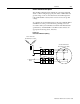
To calibrate the meter, turn the zero adjuster until the voltage
indicator needle (black) is aligned with the zero mark.
To set the trip point (for the detector relay), turn the high-set adjuster
until the orange needle points to the appropriate trip voltage. The trip
voltage should be approximately 50V higher than the maximum
reading on the meter when all the common bus inverters are
modulating.
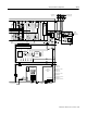
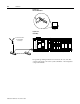
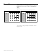
Figure 15.4
Ground-Fault Detection (Meter)
The meter will typically indicate a low voltage value (between 80 and
100V) when the inverters on the DC bus are modulating. This
voltage is produced by capacitively coupled currents to ground in the
motor’s cables and windings.
For more details on the detector wiring for your configuration, see the
system schematics. For other detector functions (such as normally-
open contacts), see the detector documentation or the detector label.
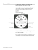
Zero Adjuster
High Set Point Adjuster
(Under Black Cap)
Voltage Indicator Needle
Trip Voltage Needle
Low Set Point Adjuster
(Not Used)
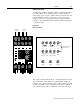
Indicator
(Coil is Energized)
Indicator
(Device is Powered)