
Owner manual


Publication 2364P-5.01 December 1999
Installation 15-5
Ground-Fault Detection Option
The parallel configuration may include the optional ground-fault
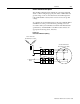
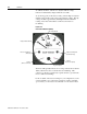
detector. When configured properly, this detector will indicate the
ground voltage on the door-mounted meter, and will energize the
relay (with NO/NC contacts) in the event of an excessive ground
voltage.
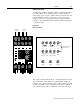
To configure the ground-fault detection relay, wire terminals TB2-1
and TB2-2 across the power transformer grounding resistor (in
accordance with system schematics and transformer manufacturer
specifications). Terminals TB1-7 and TB1-8 can be wired to an
appropriate monitoring device, if desired.
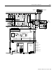
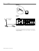
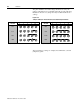
Figure 15.3
Ground-Fault Detection (Wiring)
1
2
1
2
7
8
7
8
TB2
TB1
150
Ω
10
12
2
4
Ground-Fault Detection
Meter-Relay Option (VM2)
To Monitoring
Device
Power Transformer
Grounded-Wye Secondary