
Owner manual

Publication 2364P-5.01 December 1999
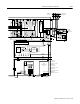
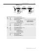
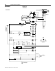
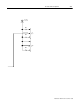
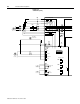
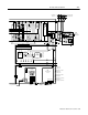
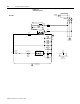
12-8 W1-Code Parallel Configuration
Figure 12.6
Schematics (cont.)
F7
MTR2
Bay 1 Door Fan
CR2
Fault
S1 - 3,
S21
TB1-9
PE
TB1-10
TB1-5 TB1-6
CR2
Fault
460VAC
(X1)
115VAC
(X2)
PT1
MTR1
RGU Door Fans
MTR3
Bay 1 Internal Fan
TB1-1
TB1-2
(JMPR)
PL2
A
14
EA10
2KHZ Control Power Filter
Choke
Thermoguards
Not
Faulted
RGU Unit Not
Faulted
Optional
Remote
Interlock
CB1-RGU
E
F
G
F4
F6
From
3-phase
AC Input
To RGU Input
Fuses (Slave)
Available for
Customer Use
To RGU Control
Circuitry (Slave)
Isolation Board
TB6 TB6
MTR9,10
Choke Bay Fans
Slave RGU