
Instruction Manual

Programming and Parameters 3-35
PowerFlex 400 Adjustable Frequency AC Drive FRN 1.xx - 7.xx User Manual
Publication 22C-UM001I-EN-P
Advanced Program Group
A141 [Purge Frequency] Related Parameter(s): P038, P039, P040, T051-T054
Provides a fixed frequency command value when T051-T054 [Digital Inx Sel] is set to 1 “Purge”. An
active purge input will override speed command as shown in the flowchart on page 1-28
.
Values Default: 5.0 Hz
Min/Max: 0.0/320.0 Hz
Display: 0.1 Hz
A142 [Internal Freq] Related Parameter(s): P038, T051-T054
Provides the frequency command to the drive when P038 [Speed Reference] is set to 1 “Internal
Freq”. When enabled, this parameter will change the frequency command in “real time” using the
digital speed keys when in program mode.
Important: Once the desired command frequency is reached, the Enter key must be pressed to store
this value to EEPROM memory. If the ESC key is used before the Enter key, the frequency will return
to the original value following the normal accel/decel curve.
If T051
- T054 [Digital Inx Sel] is set to 16 “MOP Up” or 17 “MOP Down” this parameter acts as the
MOP frequency reference if P038
[Speed Reference] is set to 1 “InternalFreq”.
Values Default: 60.00 Hz
Min/Max: 0.00/320.00 Hz
Display: 0.01 Hz
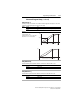
A143 [Preset Freq 0]
(1)
A144 [Preset Freq 1]
A145 [Preset Freq 2]
A146 [Preset Freq 3]
Related Parameter(s): P038, P039, P040, T051-T052,
A147
, A148
Values A143 Default:
(1)
A144 Default:
A145 Default:
A146 Default:
0.0 Hz
5.0 Hz
10.0 Hz
20.0 Hz
Min/Max: 0.0/320.0 Hz
Display: 0.1 Hz
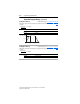
Provides a fixed frequency command value when T051
- T052 [Digital Inx Sel] is set to 8 “Preset
Freq”.
An active preset input will override speed command as shown in the flowchart on page page 1-28
.
(1)
To activate A143 [Preset Freq 0] set P038 [Speed Reference] to option 4 “Preset Freq”.
Input State of Digital In 1
(I/O Terminal 05 when
T051 = 8)
Input State of Digital In 2
(I/O Terminal 06 when
T052 = 8) Frequency Source Accel / Decel Parameter Used
(2)
0 0 A143 [Preset Freq 0] [Accel Time 1] / [Decel Time 1]
1 0 A144 [Preset Freq 1] [Accel Time 1] / [Decel Time 1]
0 1 A145 [Preset Freq 2] [Accel Time 2] / [Decel Time 2]
1 1 A146 [Preset Freq 3] [Accel Time 2] / [Decel Time 2]
(2)
When a Digital Input is set to “Accel 2 & Decel 2”, and the input is active, that input overrides the settings in
this table.