22B-UM001.book Page 1 Wednesday, January 22, 2014 11:04 AM Adjustable Frequency AC Drive FRN 1.xx - 6.xx User Manual www.abpowerflex.
2B-UM001.book Page 2 Wednesday, January 22, 2014 11:04 AM Important User Information Solid state equipment has operational characteristics differing from those of electromechanical equipment. Safety Guidelines for the Application, Installation and Maintenance of Solid State Controls (Publication SGI-1.1 available from your local Rockwell Automation sales office or online at http:// www.rockwellautomation.
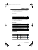
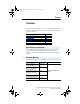
22B-UM001.book Page 1 Wednesday, January 22, 2014 11:04 AM Summary of Changes The information below summarizes the changes to the PowerFlex 40 User Manual since the August 2008 release. Manual Updates Description of New or Updated Information Minimum Enclosure Volume column and new footnotes added. Drive, Fuse & Circuit Breaker Ratings topic updated. Electronic Motor Overload Protection description updated.
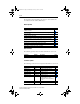
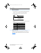
22B-UM001.book Page 2 Wednesday, January 22, 2014 11:04 AM soc-2 The information below summarizes the changes to the PowerFlex 40 User Manual since the January 2007 release. Manual Updates Description of New or Updated Information Input description and attention text for Multiple Digital Input Connection example corrected. New method of changing speed reference for IP66, NEMA/UL Type 4X rated drives described. Description for Up Arrow and Down Arrow keys revised. Fault description for F3 revised.
22B-UM001.book Page 1 Wednesday, January 22, 2014 11:04 AM Table of Contents Preface Overview Who Should Use this Manual? . . . . . . . . . Reference Materials . . . . . . . . . . . . . . . . . Manual Conventions . . . . . . . . . . . . . . . . . Drive Frame Sizes . . . . . . . . . . . . . . . . . . . General Precautions . . . . . . . . . . . . . . . . . Catalog Number Explanation . . . . . . . . . . Chapter 1 P-1 P-1 P-2 P-2 P-3 P-4 Installation/Wiring Opening the Cover . . . . . . . . . . . . . . . .
22B-UM001.book Page 2 Wednesday, January 22, 2014 11:04 AM 2 Table of Contents Appendix C RS485 (DSI) Protocol Network Wiring . . . . . . . . . . . . . . . . . . . . . Parameter Configuration . . . . . . . . . . . . . . Supported Modbus Function Codes . . . . . Writing (06) Logic Command Data. . . . . . Writing (06) Reference . . . . . . . . . . . . . . . Reading (03) Logic Status Data. . . . . . . . . Reading (03) Feedback . . . . . . . . . . . . . . . Reading (03) Drive Error Codes . . . . . . . .
22B-UM001.book Page 1 Wednesday, January 22, 2014 11:04 AM Preface Overview The purpose of this manual is to provide you with the basic information needed to install, start-up and troubleshoot the PowerFlex 40 Adjustable Frequency AC Drive. For information on… Who Should Use this Manual? Reference Materials Manual Conventions Drive Frame Sizes General Precautions Catalog Number Explanation See page… P-1 P-1 P-2 P-2 P-3 P-4 Who Should Use this Manual? This manual is intended for qualified personnel.
22B-UM001.book Page 2 Wednesday, January 22, 2014 11:04 AM P-2 Overview Manual Conventions • In this manual we refer to the PowerFlex 40 Adjustable Frequency AC Drive as; drive, PowerFlex 40 or PowerFlex 40 Drive.
22B-UM001.book Page 3 Wednesday, January 22, 2014 11:04 AM Overview P-3 General Precautions ! ATTENTION: The drive contains high voltage capacitors which take time to discharge after removal of mains supply. Before working on drive, ensure isolation of mains supply from line inputs [R, S, T (L1, L2, L3)]. Wait three minutes for capacitors to discharge to safe voltage levels. Failure to do so may result in personal injury or death.
22B-UM001.book Page 4 Wednesday, January 22, 2014 11:04 AM P-4 Overview Catalog Number Explanation 1-3 4 5 6-8 22B - A 1P5 Drive Dash Voltage Rating Rating 9 10 11 12 (1) N 1 1 4 Enclosure HIM Emission Class Type Code 22B PowerFlex 40 Code V A B D E Voltage 120V AC 240V AC 240V AC 480V AC 600V AC Code Rating 0 Not Filtered 1 Filtered Ph.
22B-UM001.book Page 1 Wednesday, January 22, 2014 11:04 AM Chapter 1 Installation/Wiring This chapter provides information on mounting and wiring the PowerFlex 40 Drive.
22B-UM001.book Page 2 Wednesday, January 22, 2014 11:04 AM 1-2 Installation/Wiring IP66, NEMA/UL Type 4X ! ATTENTION: To avoid an electric shock hazard, ensure isolation of mains supply from line inputs [R, S, T (L1, L2, L3)] and wait three minutes for capacitors to discharge before removing the external cover. Once the cover is removed, verify that the voltage on the bus capacitors has discharged before performing any work on the drive.
22B-UM001.book Page 3 Wednesday, January 22, 2014 11:04 AM Installation/Wiring 1-3 Mounting Considerations • Mount the drive upright on a flat, vertical and level surface. Frame B C B (IP66, Type 4X) • • • Screw Size M4 (#8-32) M5 (#10-24) Screw Torque 1.56-1.96 N-m (14-17 lb.-in.) 2.45-2.94 N-m (22-26 lb.-in.) DIN Rail 35 mm – M6 (#12-24) 3.95-4.75 N-m (35-42 lb.-in.) – Protect the cooling fan by avoiding dust or metallic particles. Do not expose to a corrosive atmosphere.
22B-UM001.book Page 4 Wednesday, January 22, 2014 11:04 AM 1-4 Installation/Wiring Debris Protection A plastic top panel is included with the drive. Install the panel to prevent debris from falling through the vents of the drive housing during installation. Remove the panel for IP20, NEMA/UL Type Open applications. Storage • • • Store within an ambient temperature range of -40° to +85°C. Store within a relative humidity range of 0% to 95%, non-condensing. Do not expose to a corrosive atmosphere.
22B-UM001.book Page 5 Wednesday, January 22, 2014 11:04 AM Installation/Wiring 1-5 AC Supply Source Considerations Ungrounded Distribution Systems ! ATTENTION: PowerFlex 40 drives contain protective MOVs that are referenced to ground. These devices must be disconnected if the drive is installed on an ungrounded or resistive grounded distribution system.
22B-UM001.book Page 6 Wednesday, January 22, 2014 11:04 AM 1-6 Installation/Wiring Input Power Conditioning The drive is suitable for direct connection to input power within the rated voltage of the drive (see Appendix A). Listed in Table 1.B are certain input power conditions which may cause component damage or reduction in product life. If any of the conditions exist, as described in Table 1.B, install one of the devices listed under the heading Corrective Action on the line side of the drive.
22B-UM001.book Page 7 Wednesday, January 22, 2014 11:04 AM Installation/Wiring 1-7 General Grounding Requirements The drive Safety Ground (PE) must be connected to system ground. Ground impedance must conform to the requirements of national and local industrial safety regulations and/or electrical codes. The integrity of all ground connections should be periodically checked. Figure 1.
22B-UM001.book Page 8 Wednesday, January 22, 2014 11:04 AM 1-8 Installation/Wiring RFI Filter Grounding Using single phase drives with integral filter, or an external filter with any drive rating, may result in relatively high ground leakage currents. Therefore, the filter must only be used in installations with grounded AC supply systems and be permanently installed and solidly grounded (bonded) to the building power distribution ground.
22B-UM001.book Page 9 Wednesday, January 22, 2014 11:04 AM Installation/Wiring 1-9 Table 1.C Minimum Recommended Branch Circuit Protective Devices Voltage Rating Drive Rating kW (HP) Recommended Min. Enclosure Fuse Rating(1) 140M Motor Amps Protectors(2) (3) MCS Contactors Volume(4) Catalog No. Catalog No. Inches3 120V AC – 1-Phase 0.4 (0.5) 0.75 (1.0) 1.1 (1.5) 15 35 40 140M-C2E-C16 100-C12 140M-D8E-C20 100-C23 140M-F8E-C32 100-C37 1655 1655 1655 240V AC – 1-Phase 0.4 (0.5) 0.75 (1.0) 1.5 (2.
22B-UM001.book Page 10 Wednesday, January 22, 2014 11:04 AM 1-10 Installation/Wiring Power Wiring ! ! ATTENTION: National Codes and standards (NEC, VDE, BSI, etc.) and local codes outline provisions for safely installing electrical equipment. Installation must comply with specifications regarding wire types, conductor sizes, branch circuit protection and disconnect devices. Failure to do so may result in personal injury and/or equipment damage.
22B-UM001.book Page 11 Wednesday, January 22, 2014 11:04 AM Installation/Wiring 1-11 Shielded cable may also help reduce shaft voltage and induced bearing currents for some applications. In addition, the increased impedance of shielded cable may help extend the distance that the motor can be located from the drive without the addition of motor protective devices such as terminator networks. Refer to Reflected Wave in “Wiring and Grounding Guidelines for PWM AC Drives,” publication DRIVES-IN001A-EN-P.
B-UM001.book Page 12 Wednesday, January 22, 2014 11:04 AM 1-12 Installation/Wiring Reflected Wave Protection The drive should be installed as close to the motor as possible. Installations with long motor cables may require the addition of external devices to limit voltage reflections at the motor (reflected wave phenomena). See Table 1.D for recommendations. The reflected wave data applies to all frequencies 2 to 16 kHz. For 240V ratings, reflected wave effects do not need to be considered. Table 1.
22B-UM001.book Page 13 Wednesday, January 22, 2014 11:04 AM Installation/Wiring 1-13 Power Terminal Block The power terminal block is covered by a finger guard. To remove: 1. Press in and hold the locking tab. 2. Slide finger guard down and out. Replace the finger guard when wiring is complete. Figure 1.
22B-UM001.book Page 14 Wednesday, January 22, 2014 11:04 AM 1-14 Installation/Wiring IP66, NEMA/UL Type 4X Installations Use the plugs supplied with IP66, NEMA/UL Type 4X rated drives to seal unused holes in the conduit entry plate. Important: Completely seat the plug inner rim for the best seal.
22B-UM001.book Page 15 Wednesday, January 22, 2014 11:04 AM Installation/Wiring 1-15 Control Wire Types Table 1.F Recommended Control and Signal Wire(1) Wire Type(s)(2) Description Belden 8760/9460 (or equiv.) 0.8 mm2 (18AWG), twisted pair, 100% shield with drain. (1) Belden 8770 (or equiv.) (1) (2) Minimum Insulation Rating 300V 60 degrees C 0.8 mm2 (18AWG), 3 conductor, shielded for (140 degrees F) remote pot only.
22B-UM001.book Page 16 Wednesday, January 22, 2014 11:04 AM 1-16 Installation/Wiring Figure 1.5 Control Wiring Block Diagram Enable Jumper (4) 01 02 03 SNK SRC 04 05 06 07 08 09 +24V 11 +10V 12 13 14 Relay N.O. Relay Common Relay N.C.
22B-UM001.book Page 17 Wednesday, January 22, 2014 11:04 AM Installation/Wiring 1-17 Table 1.H Control I/O Terminal Designations No. Signal Default Description Param. R1 Relay N.O. Fault Normally open contact for output relay. A055 R2 Relay Common – Common for output relay. R3 Relay N.C. Fault Normally closed contact for output relay. A055 Analog Output Select DIP 0-10V Switch Sets analog output to either voltage or current. Setting must match A065 [Analog Out Sel].
22B-UM001.book Page 18 Wednesday, January 22, 2014 11:04 AM 1-18 Installation/Wiring I/O Wiring Examples Input/Output Potentiometer 1-10k Ohm Pot.
22B-UM001.book Page 19 Wednesday, January 22, 2014 11:04 AM Installation/Wiring Input/Output Connection Example 2 Wire SRC Control - Internal Supply (SRC) Non-Reversing 11 P036 [Start Source] = 2, 3 or 4 Input must be active for Stop-Run the drive to run. When input is opened, the drive will stop as specified by P037 [Stop Mode]. If desired, a User Supplied 24V DC power source can be used. Refer to the “External Supply (SRC)” example.
22B-UM001.book Page 20 Wednesday, January 22, 2014 11:04 AM 1-20 Installation/Wiring Input/Output Connection Example 2 Wire SNK Control - Internal Supply (SNK) Run FWD/Run REV Stop-Run Forward 01 02 03 04 Stop-Run Reverse 3 Wire SRC Control - Internal Supply (SRC) Non-Reversing P036 [Start Source] = 1 Stop 11 A momentary input will start the drive. A stop Start input to I/O Terminal 01 will stop the drive as specified by P037 [Stop Mode].
22B-UM001.book Page 21 Wednesday, January 22, 2014 11:04 AM Installation/Wiring 1-21 Input/Output Connection Example 3 Wire SNK Control - Internal Supply (SNK) Reversing Stop 01 02 03 04 Start Direction Opto Output (1 & 2) A058 [Opto Out1 Sel] determines Opto-Output 1 (I/O Terminal 17) operation. A061 [Opto Out2 Sel] determines Opto-Output 2 (I/O Terminal 18) operation.
22B-UM001.book Page 22 Wednesday, January 22, 2014 11:04 AM 1-22 Installation/Wiring Typical Multiple Drive Connection Examples Input/Output Connection Example Multiple Digital 02 04 Input Connections Customer Inputs can be wired per External Supply (SRC) examples on 1-19 and 1-20.
22B-UM001.book Page 23 Wednesday, January 22, 2014 11:04 AM Installation/Wiring 1-23 Start and Speed Reference Control The drive speed command can be obtained from a number of different sources. The source is normally determined by P038 [Speed Reference]. However, when A051 - A054 [Digital Inx Sel] is set to option 2, 4, 5, 6, 11, 12, 13, 14, 15 and the digital input is active, or if A132 is not set to option 0, the speed reference commanded by P038 [Speed Reference] will be overridden.
22B-UM001.book Page 24 Wednesday, January 22, 2014 11:04 AM 1-24 Installation/Wiring Accel/Decel Selection The Accel/Decel rate can be obtained by a variety of methods. The default rate is determined by P039 [Accel Time 1] and P040 [Decel Time 1]. Alternative Accel/Decel rates can be made through digital inputs, RS485 (DSI) communications and/or parameters. See the chart below for the override priority.
22B-UM001.book Page 25 Wednesday, January 22, 2014 11:04 AM Installation/Wiring 1-25 EMC Instructions CE Conformity Conformity with the Low Voltage (LV) Directive and Electromagnetic Compatibility (EMC) Directive has been demonstrated using harmonized European Norm (EN) standards published in the Official Journal of the European Communities. PowerFlex Drives comply with the EN standards listed below when installed according to the User Manual.
22B-UM001.book Page 26 Wednesday, January 22, 2014 11:04 AM 1-26 Installation/Wiring Essential Requirements for CE Compliance Conditions 1-3 listed below must be satisfied for PowerFlex drives to meet the requirements of EN61800-3. 1. Grounding as described in Figure 1.6. Refer to page 1-8 for additional grounding recommendations. 2. Output power, control (I/O) and signal wiring must be braided, shielded cable with a coverage of 75% or better, metal conduit or equivalent attenuation. 3.
22B-UM001.book Page 27 Wednesday, January 22, 2014 11:04 AM Installation/Wiring 1-27 EN61000-3-2 • • 0.75 kW (1 HP) 240V 1-Phase and 3-Phase drives and 0.37 kW (0.5 HP) 240V 1-Phase drives are suitable for installation on a private low voltage power network. Installations on a public low voltage power network may require additional external harmonic mitigation. Other drive ratings meet the current harmonic requirements of EN61000-3-2 without additional external mitigation.
22B-UM001.book Page 28 Wednesday, January 22, 2014 11:04 AM 1-28 Installation/Wiring Notes: PowerFlex 40 Adjustable Frequency AC Drive FRN 1.xx - 6.
22B-UM001.book Page 1 Wednesday, January 22, 2014 11:04 AM Chapter 2 Start Up This chapter describes how to start up the PowerFlex 40 Drive. To simplify drive setup, the most commonly programmed parameters are organized in a single Basic Program Group. Important: Read the General Precautions section before proceeding. ! ATTENTION: Power must be applied to the drive to perform the following start-up procedures. Some of the voltages present are at incoming line potential.
22B-UM001.book Page 2 Wednesday, January 22, 2014 11:04 AM 2-2 Start Up Applying Power to the Drive ❏ 6. Apply AC power and control voltages to the drive. ❏ 7. Familiarize yourself with the integral keypad features (see page 2-4) before setting any Program Group parameters. If a fault appears on power up, refer to Fault Descriptions on page 4-3 for an explanation of the fault code.
22B-UM001.book Page 3 Wednesday, January 22, 2014 11:04 AM Start Up 2-3 TIP: You can also change the speed reference by editing the parameter A069 [Internal Freq] in program mode. For details on how to enter the program mode, see Viewing and Editing Parameters on page 2-5. Note: The default value of A069 [Internal Freq] is 0 Hz. For IP20 rated PowerFlex 40 drives, the default value of this parameter is 60 Hz.
22B-UM001.book Page 4 Wednesday, January 22, 2014 11:04 AM 2-4 Start Up Integral Keypad ➋ ➊ ➌ RUN FWD REV ➎ Basic Program Group Consists of most commonly used programmable functions. ➑ ➐ Description Display Group (View Only) Consists of commonly viewed drive operating conditions. FAULT PROGRAM ➍ ➏ Menu VOLTS AMPS HERTZ ➒ Advanced Program Group Consists of remaining programmable functions. Fault Designator Consists of list of codes for specific fault conditions.
22B-UM001.book Page 5 Wednesday, January 22, 2014 11:04 AM Start Up 2-5 Viewing and Editing Parameters The last user-selected Display Group parameter is saved when power is removed and is displayed by default when power is reapplied. The following is an example of basic integral keypad and display functions. This example provides basic navigation instructions and illustrates how to program the first Program Group parameter. Step Key(s) 1.
22B-UM001.book Page 6 Wednesday, January 22, 2014 11:04 AM 2-6 Start Up The Basic Program Group (page 3-9) contains the most commonly changed parameters.
22B-UM001.book Page 7 Wednesday, January 22, 2014 11:04 AM Start Up 2-7 Diagnostics Menu When a fault trips the drive, use this menu to access detailed data about the drive. Option Faults Device Status Device Version Description View fault queue or fault information, clear faults or clear fault queue. View status information about the drive or peripheral. View the firmware version and hardware series of components. Parameters Menu Use this menu to access drive parameters.
22B-UM001.book Page 8 Wednesday, January 22, 2014 11:04 AM 2-8 Start Up Notes: PowerFlex 40 Adjustable Frequency AC Drive FRN 1.xx - 6.
22B-UM001.book Page 1 Wednesday, January 22, 2014 11:04 AM Chapter 3 Programming and Parameters Chapter 3 provides a complete listing and description of the PowerFlex 40 parameters. Parameters are programmed (viewed/edited) using the integral keypad. As an alternative, programming can also be performed using DriveExplorer™ or DriveExecutive™ software, a personal computer and a serial converter module. Refer to Appendix B for catalog numbers.
22B-UM001.book Page 2 Wednesday, January 22, 2014 11:04 AM 3-2 Programming and Parameters Parameter Organization Refer to page 3-45 for an alphabetical listing of parameters.
22B-UM001.book Page 3 Wednesday, January 22, 2014 11:04 AM Programming and Parameters 3-3 Display Group d001 [Output Freq] Related Parameter(s): d002, d010, P034, P035, P038 Output frequency present at T1, T2 & T3 (U, V & W). Values Default: Read Only Min/Max: 0.0/P035 [Maximum Freq] Display: 0.1 Hz d002 [Commanded Freq] Related Parameter(s): d001, d013, P034, P035, P038 Value of the active frequency command. Displays the commanded frequency even if the drive is not running.
22B-UM001.book Page 4 Wednesday, January 22, 2014 11:04 AM 3-4 Programming and Parameters Display Group (continued) d006 [Drive Status] Related Parameter(s): A095 Present operating condition of the drive. Running Forward Accelerating Decelerating Values 1 = Condition True, 0 = Condition False Bit 0 Bit 1 Bit 2 Bit 3 Default: Read Only Min/Max: 0/1 Display: 1 d007 [Fault 1 Code] d008 [Fault 2 Code] d009 [Fault 3 Code] A code that represents a drive fault.
22B-UM001.book Page 5 Wednesday, January 22, 2014 11:04 AM Programming and Parameters 3-5 Display Group (continued) d012 [Control Source] Related Parameter(s): P036, P038, A051-A054 Displays the active source of the Start Command and Speed Command which are normally defined by the settings of P036 [Start Source] and P038 [Speed Reference] but may be overridden by digital inputs. Refer to the flowcharts on pages 1-23 and 1-24 for details.
22B-UM001.book Page 6 Wednesday, January 22, 2014 11:04 AM 3-6 Programming and Parameters Display Group (continued) d014 [Dig In Status] Related Parameter(s): A051-A054 Status of the control terminal block digital inputs.
22B-UM001.book Page 7 Wednesday, January 22, 2014 11:04 AM Programming and Parameters 3-7 Display Group (continued) d018 [Elapsed Run Time] Accumulated time drive is outputting power. Time is displayed in 10 hour increments. Values Default: Read Only Min/Max: 0/9999 Hrs Display: 1 = 10 Hrs d019 [Testpoint Data] Related Parameter(s): A102 The present value of the function selected in A102 [Testpoint Sel].
22B-UM001.book Page 8 Wednesday, January 22, 2014 11:04 AM 3-8 Programming and Parameters Display Group (continued) d024 [Drive Temp] Present operating temperature of the drive power section. Values Default: Read Only Min/Max: 0/120 degC Display: 1 degC d025 [Counter Status] The current value of the counter when counter is enabled. Values Default: Read only Min/Max: 0/9999 Display: 1 d026 [Timer Status] 32 32 bit parameter. The current value of the timer when timer is enabled.
22B-UM001.book Page 9 Wednesday, January 22, 2014 11:04 AM Programming and Parameters 3-9 Basic Program Group P031 [Motor NP Volts] Related Parameter(s): d004, A084, A085, A086, A087 Stop drive before changing this parameter. Set to the motor nameplate rated volts. Values Default: Based on Drive Rating Min/Max: 20/Drive Rated Volts Display: 1 VAC P032 [Motor NP Hertz] Related Parameter(s): A084, A085, A086, A087, A090 Stop drive before changing this parameter.
22B-UM001.book Page 10 Wednesday, January 22, 2014 11:04 AM 3-10 Programming and Parameters Basic Program Group (continued) P036 [Start Source] Related Parameter(s): d012, P037 Stop drive before changing this parameter. Sets the control scheme used to start the drive. Refer to Start and Speed Reference Control on page 1-23 for details about how other drive settings can override the setting of this parameter.
22B-UM001.book Page 11 Wednesday, January 22, 2014 11:04 AM Programming and Parameters 3-11 Basic Program Group (continued) P037 [Stop Mode] Related Parameter(s): P036, A080, A081, A082, A105, A160 Active stop mode for all stop sources [e.g. keypad, run forward (I/O Terminal 02), run reverse (I/O Terminal 03), RS485 port] except as noted below. Important: I/O Terminal 01 is always a coast to stop input except when P036 [Start Source] is set for “3-Wire” control.
22B-UM001.book Page 12 Wednesday, January 22, 2014 11:04 AM 3-12 Programming and Parameters Basic Program Group (continued) P038 [Speed Reference] Related Parameter(s): d001, d002, d012, d020, d021, P039, P040, A051-A054, A069, A070-A077, A110-A113, A123, A132, A140-A147, A150-A157 Sets the source of the speed reference to the drive. The drive speed command can be obtained from a number of different sources. The source is normally determined by P038 [Speed Reference].
22B-UM001.book Page 13 Wednesday, January 22, 2014 11:04 AM Programming and Parameters 3-13 Basic Program Group (continued) P040 [Decel Time 1] Related Parameter(s): P038, P039, A051-A054, A068, A070-A077, A140-A147 Sets the rate of deceleration for all speed decreases. Maximum Freq = Decel Rate Decel Time Values Default: 10.0 Secs Min/Max: 0.1/600.0 Secs Display: 0.
22B-UM001.book Page 14 Wednesday, January 22, 2014 11:04 AM 3-14 Programming and Parameters Advanced Program Group A051 [Digital In1 Sel] (I/O Terminal 05) Related Parameter(s): d012, d014, P038, P039, P040, A067, A068, A070-A077, A078, A079, A118, A140-A147 A052 [Digital In2 Sel] (I/O Terminal 06) A053 [Digital In3 Sel] Stop drive before changing this parameter. (I/O Terminal 07) A054 [Digital In4 Sel] (I/O Terminal 08) Selects the function for the digital inputs.
22B-UM001.book Page 15 Wednesday, January 22, 2014 11:04 AM Programming and Parameters A051 13 “10V In Ctrl” A054 Options 14 “20mA In Ctrl” (Cont.) 15 “PID Disable” 16 “MOP Up” 17 “MOP Down” 18 “Timer Start” 19 “Counter In” 20 21 22 23 “Reset Timer” “Reset Countr” “Rset Tim&Cnt” “Logic In1” 24 “Logic In2” 25 “Current Lmt2” 26 “Anlg Invert” 27 “EM Brk Rlse” ! 3-15 Selects 0-10V or ±10V control as the frequency reference. Start source is not changed.
22B-UM001.book Page 16 Wednesday, January 22, 2014 11:04 AM 3-16 Programming and Parameters Advanced Program Group (continued) A055 [Relay Out Sel] Related Parameter(s): P033, A056, A092, A140-A147, A150-A157, A160, A161 Sets the condition that changes the state of the output relay contacts. Options 0 “Ready/Fault” Relay changes state when power is applied. This indicates that the drive is ready for operation. Relay returns drive to (Default) shelf state when power is removed or a fault occurs.
22B-UM001.book Page 17 Wednesday, January 22, 2014 11:04 AM Programming and Parameters A055 19 “Anlg In Loss” Options (Cont.) 20 “ParamControl” 3-17 Analog input loss has occurred. Program A122 [Analog In Loss] for desired action when input loss occurs. Prior to FRN 4.01, this option enables the output to be controlled over network communications by writing to A056 [Relay Out Level]. (0 = Off, 1 = On.) With FRN 4.01 and later, the logic command word bit 15 has full control of A056.
22B-UM001.book Page 18 Wednesday, January 22, 2014 11:04 AM 3-18 Programming and Parameters Advanced Program Group (continued) A058 [Opto Out1 Sel] A061 [Opto Out2 Sel] Related Parameter(s): P033, A059, A062, A092, A122, A123, A160, A161, A140-A147, A150-A157 Determines the operation of the programmable opto outputs. Options 0 “Ready/Fault” Opto outputs are active when power is applied. This indicates that the drive is ready for operation.
22B-UM001.book Page 19 Wednesday, January 22, 2014 11:04 AM Programming and Parameters 3-19 A058, 18 “Above PF Ang” A061 Options (Cont.) 19 “Anlg In Loss” • Power Factor angle has exceeded the value set in A059 or A062 [Opto Outx Level]. • Use A059 or A062 to set threshold. Analog input loss has occurred. Program A122 [Analog In Loss] for desired action when input loss occurs. 20 “ParamControl” Prior to FRN 4.
22B-UM001.book Page 20 Wednesday, January 22, 2014 11:04 AM 3-20 Programming and Parameters Advanced Program Group (continued) A064 [Opto Out Logic] Determines the logic (Normally Open/NO or Normally Closed/NC) of the opto outputs.
22B-UM001.book Page 21 Wednesday, January 22, 2014 11:04 AM Programming and Parameters 3-21 Advanced Program Group (continued) A066 [Analog Out High] Related Parameter(s): A065 Scales the Maximum Output Value for the A065 [Analog Out Sel] source setting. Examples: A066 Setting 50% 90% Values A065 Setting 1 “OutCurr 0-10” 8 “OutPowr 0-20” A065 Max.
22B-UM001.book Page 22 Wednesday, January 22, 2014 11:04 AM 3-22 Programming and Parameters Advanced Program Group (continued) A068 [Decel Time 2] Related Parameter(s): P040, A051-A054, A070-A077, A140-A147 When active, sets the rate of deceleration for all speed decreases except jog. Refer to the flowchart on page 1-24 for details. Maximum Freq = Decel Rate Decel Time Values Default: 20.0 Secs Min/Max: 0.1/600.0 Secs Display: 0.
22B-UM001.book Page 23 Wednesday, January 22, 2014 11:04 AM Programming and Parameters 3-23 Advanced Program Group (continued) A070 [Preset Freq 0](1) A071 [Preset Freq 1] A072 [Preset Freq 2] A073 [Preset Freq 3] A074 [Preset Freq 4] A075 [Preset Freq 5] A076 [Preset Freq 6] A077 [Preset Freq 7] A070 Default:(1) A071 Default: A072 Default: A073 Default: A074 Default: A075 Default: A076 Default: A077 Default: Values Related Parameter(s): P038, P039, P040, A051-A053, A067, A068, A140-A147, A150-A157 0.
22B-UM001.book Page 24 Wednesday, January 22, 2014 11:04 AM 3-24 Programming and Parameters Advanced Program Group (continued) A079 [Jog Accel/Decel] Related Parameter(s): A078, A051-A054 Sets the acceleration and deceleration time when a jog command is issued. Values Default: 10.0 Secs Min/Max: 0.1/600.0 Secs Display: 0.1 Secs A080 [DC Brake Time] Related Parameter(s): P037, A081 Sets the length of time that DC brake current is “injected” into the motor.
22B-UM001.book Page 25 Wednesday, January 22, 2014 11:04 AM Programming and Parameters 3-25 Advanced Program Group (continued) A082 [DB Resistor Sel] Related Parameter(s): P037 Stop drive before changing this parameter. Enables/disables external dynamic braking. Setting 0 1 2 3-99 Min/Max “Disabled” “Normal RA Res” (5% Duty Cycle) – Refer to Table B.C on page B-2. “NoProtection” (100% Duty Cycle) “x%Duty Cycle” Limited (3% – 99% of Duty Cycle) The drive is able to provide full braking indefinitely.
22B-UM001.book Page 26 Wednesday, January 22, 2014 11:04 AM 3-26 Programming and Parameters Advanced Program Group (continued) A084 [Boost Select] Related Parameter(s): d004, P031, P032, A085, A086, A087, A125 Sets the boost voltage (% of P031 [Motor NP Volts]) and redefines the Volts per Hz curve. Active when A125 [Torque Perf Mode] = 0 “V/Hz”. Drive may add additional voltage unless Option 5 is selected. Options 0 “Custom V/Hz” 1 “30.0, VT” 2 “35.0, VT” Variable Torque (Typical fan/pump curves.
22B-UM001.book Page 27 Wednesday, January 22, 2014 11:04 AM Programming and Parameters 3-27 Advanced Program Group (continued) A085 [Start Boost] Related Parameter(s): P031, P032, P034, P035, A084, A086, A087, A088, A125 Sets the boost voltage (% of P031 [Motor NP Volts]) and redefines the Volts per Hz curve when A084 [Boost Select] = 0 “Custom V/Hz” and A125 [Torque Perf Mode] = 0 “V/Hz”. Drive may add additional voltage unless Option 5 is selected. Values Default: 2.5% Min/Max: 0.0/25.
22B-UM001.book Page 28 Wednesday, January 22, 2014 11:04 AM 3-28 Programming and Parameters Advanced Program Group (continued) A088 [Maximum Voltage] Related Parameter(s): d004, A085, A086, A087 Sets the highest voltage the drive will output. Values Default: Drive Rated Volts Min/Max: 20/Drive Rated Volts Display: 1 VAC A089 [Current Limit 1] Related Parameter(s): P033, A118 Maximum output current allowed before current limiting occurs. Values Drive Rated Amps × 1.5 Default: Min/Max: 0.
22B-UM001.book Page 29 Wednesday, January 22, 2014 11:04 AM Programming and Parameters 3-29 Advanced Program Group (continued) A092 [Auto Rstrt Tries] Related Parameter(s): A055, A058, A061, A093 Sets the maximum number of times the drive attempts to reset a fault and restart. Clear a Type 1 fault and restart the drive. 1. Set A092 [Auto Rstrt Tries] to a value other than “0”. 2. Set A093 [Auto Rstrt Delay] to a value other than “0”.
22B-UM001.book Page 30 Wednesday, January 22, 2014 11:04 AM 3-30 Programming and Parameters Advanced Program Group (continued) A095 [Reverse Disable] Related Parameter(s): d006 Stop drive before changing this parameter. Enables/disables the function that allows the direction of motor rotation to be changed. The reverse command may come from a digital command, the keypad or a serial command. All reverse inputs including two-wire Run Reverse will be ignored with reverse disabled.
22B-UM001.book Page 31 Wednesday, January 22, 2014 11:04 AM Programming and Parameters 3-31 Advanced Program Group (continued) A100 [Fault Clear] Stop drive before changing this parameter. Resets a fault and clears the fault queue. Used primarily to clear a fault over network communications. Options 0 “Ready/Idle” (Default) 1 “Reset Fault” 2 “Clear Buffer” (Parameters d007-d009 [Fault x Code]) A101 [Program Lock] Protects parameters against change by unauthorized personnel.
22B-UM001.book Page 32 Wednesday, January 22, 2014 11:04 AM 3-32 Programming and Parameters Advanced Program Group (continued) A105 [Comm Loss Action] Related Parameter(s): d015, P037, A106 Selects the drive’s response to a loss of the communication connection or excessive communication errors. Options 0 “Fault” (Default) Drive will fault on an F81 Comm Loss and coast to stop. 1 “Coast Stop” Stops drive via coast to stop. 2 “Stop” Stops drive via P037 [Stop Mode] setting.
22B-UM001.book Page 33 Wednesday, January 22, 2014 11:04 AM Programming and Parameters 3-33 Advanced Program Group (continued) A109 [Anlg Out Setpt] Related Parameter(s): A065 When A065 [Analog Out Sel] is set to option 18, 19 or 20, this parameter sets the percentage of analog output desired. Values Default: 0.0% Min/Max: 0.0/100.0% Display: 0.
22B-UM001.book Page 34 Wednesday, January 22, 2014 11:04 AM 3-34 Programming and Parameters Advanced Program Group (continued) A113 [Anlg In4-20mA Hi] Related Parameter(s): d021, P035, P038 Sets the analog input level that corresponds to P035 [Maximum Freq] if a 4-20mA input is used by P038 [Speed Reference]. Analog inversion can be accomplished by setting this value smaller than A112 [Anlg In4-20mA Lo]. Values Default: 100.0% Min/Max: 0.0/100.0% Display: 0.
22B-UM001.book Page 35 Wednesday, January 22, 2014 11:04 AM Programming and Parameters 3-35 Advanced Program Group (continued) A119 [Skip Frequency] Related Parameter(s): A120 Sets the frequency at which the drive will not operate. A setting of 0 disables this parameter. Values Default: 0 Hz Min/Max: 0/400 Hz Display: 1 Hz A120 [Skip Freq Band] Related Parameter(s): A119 Determines the bandwidth around A119 [Skip Frequency].
22B-UM001.book Page 36 Wednesday, January 22, 2014 11:04 AM 3-36 Programming and Parameters Advanced Program Group (continued) A122 [Analog In Loss] Related Parameter(s): A110, A111, A132 Selects drive action when an input signal loss is detected. Signal loss is defined as an analog signal less than 1V or 2mA. The signal loss event ends and normal operation resumes when the input signal level is greater than or equal to 1.5V or 3mA.
22B-UM001.book Page 37 Wednesday, January 22, 2014 11:04 AM Programming and Parameters 3-37 Advanced Program Group (continued) A127 [Autotune] Related Parameter(s): A125, A126, A128, A129 Stop drive before changing this parameter. Provides an automatic method for setting A128 [IR Voltage Drop] and A129 [Flux Current Ref], which affect sensorless vector performance. Parameter A126 [Motor NP FLA] must be set to the motor nameplate full load amps before running the Autotune procedure.
22B-UM001.book Page 38 Wednesday, January 22, 2014 11:04 AM 3-38 Programming and Parameters Advanced Program Group (continued) A130 [PID Trim Hi] Sets the maximum positive value that is added to the speed reference when PID trim is used. Values Default: 60.0 Min/Max: 0.0/400.0 Display: 0.1 A131 [PID Trim Lo] Sets the maximum positive value that is subtracted from the PID reference when PID trim is used. Values Default: 0.0 Min/Max: 0.0/400.0 Display: 0.
22B-UM001.book Page 39 Wednesday, January 22, 2014 11:04 AM Programming and Parameters 3-39 Advanced Program Group (continued) A135 [PID Integ Time] Sets the value for the PID integral component when the PID mode is enabled by A132 [PID Ref Sel]. Values Default: 0.1 Secs Min/Max: 0.0/999.9 Secs Display: 0.1 Secs A136 [PID Diff Rate] Sets the value for the PID differential component when the PID mode is enabled by A132 [PID Ref Sel]. Values Default: 0.01 (1/Secs) Min/Max: 0.00/99.
22B-UM001.book Page 40 Wednesday, January 22, 2014 11:04 AM 3-40 Programming and Parameters Advanced Program Group (continued) A140 [Stp Logic 0] A141 [Stp Logic 1] A142 [Stp Logic 2] A143 [Stp Logic 3] A144 [Stp Logic 4] A145 [Stp Logic 5] A146 [Stp Logic 6] A147 [Stp Logic 7] Values Default: Related Parameter(s): P038, P039, P040, A051-A054, A055, A058, A061, A067, A068, A070-A077, A150-A157 Stop drive before changing this parameter.
22B-UM001.book Page 41 Wednesday, January 22, 2014 11:04 AM Programming and Parameters 3-41 Digit 3: Step Settings This digit defines what accel/decel profile the speed command will follow and the direction of the command for the current step. In addition, if a relay or opto output (parameters A055, A058 and A061) is set to 15 “StpLogic Out”, this parameter can control the status of that output.
22B-UM001.book Page 42 Wednesday, January 22, 2014 11:04 AM 3-42 Programming and Parameters Advanced Program Group (continued) A150 [Stp Logic Time 0] A151 [Stp Logic Time 1] A152 [Stp Logic Time 2] A153 [Stp Logic Time 3] A154 [Stp Logic Time 4] A155 [Stp Logic Time 5] A156 [Stp Logic Time 6] A157 [Stp Logic Time 7] Related Parameter(s): P038, A055, A058, A061, A070-A077, A140-A147 Sets the time to remain in each step if the corresponding StpLogic command word is set to “Step after Time”.
22B-UM001.book Page 43 Wednesday, January 22, 2014 11:04 AM Programming and Parameters 3-43 Advanced Program Group (continued) A161 [EM Brk On Delay] Related Parameter(s): P037 Sets the time the drive remains at minimum frequency before the relay or an opto output is de-energizing and the drive stops. The relay or opto output is typically connected to a user-supplied electromechanical brake coil relay.
22B-UM001.book Page 44 Wednesday, January 22, 2014 11:04 AM 3-44 Programming and Parameters Advanced Program Group (continued) A164 [Comm Write Mode] Determines whether parameter changes made over communication port are saved and stored in Non-Volatile Storage (NVS) or RAM only. If they are stored in RAM, the values will be lost at power-down. Options 0 “Save” (Default) 1 “RAM Only” ! ATTENTION: Risk of equipment damage exists.
22B-UM001.book Page 45 Wednesday, January 22, 2014 11:04 AM Programming and Parameters 3-45 Parameter Cross Reference – by Name Parameter Name No. Group Parameter Name No.
22B-UM001.book Page 46 Wednesday, January 22, 2014 11:04 AM 3-46 Programming and Parameters Parameter Name No. Group Testpoint Data Testpoint Sel Timer Status Torque Current Torque Perf Mode Var PWM Disable Voltage Class d019 A102 d026 d029 A125 A124 P042 Display Advanced Program Display Display Advanced Program Advanced Program Basic Program PowerFlex 40 Adjustable Frequency AC Drive FRN 1.xx - 6.
22B-UM001.book Page 1 Wednesday, January 22, 2014 11:04 AM Chapter 4 Troubleshooting Chapter 4 provides information to guide you in troubleshooting the PowerFlex 40 drive. Included is a listing and description of drive faults (with possible solutions, when applicable). For information on… Drive Status Faults See page… For information on… 4-1 Fault Descriptions 4-1 Common Symptoms and Corrective Actions See page… 4-3 4-5 Drive Status The condition or state of your drive is constantly monitored.
22B-UM001.book Page 2 Wednesday, January 22, 2014 11:04 AM 4-2 Troubleshooting Fault Indication Condition Display Drive is indicating a fault. The integral keypad provides visual notification of a fault condition by displaying the following. • Flashing fault number • Flashing fault indicator Press the Escape key to regain control of the integral keypad. RUN FWD REV VOLTS AMPS HERTZ PRGOGRAM FAULT Manually Clearing Faults Step Key(s) 1. Press Esc to acknowledge the fault.
22B-UM001.book Page 3 Wednesday, January 22, 2014 11:04 AM Troubleshooting 4-3 Fault Descriptions Type(1) Table 4.A Fault Types, Descriptions and Actions No. F2 Fault Auxiliary Input F3 Power Loss ➁ F4 UnderVoltage ➀ F5 OverVoltage ➀ F6 Motor Stalled ➀ F7 Motor Overload ➀ F8 Heatsink OvrTmp ➀ F12 HW OverCurrent ➁ F13 Ground Fault ➁ F29 Analog Input Loss ➀ ➀ Description Auxiliary input interlock is open. Action 1. Check remote wiring. 2.
22B-UM001.book Page 4 Wednesday, January 22, 2014 11:04 AM (1) Troubleshooting See page 4-1 for a description of fault types. Type(1) 4-4 No.
22B-UM001.book Page 5 Wednesday, January 22, 2014 11:04 AM No. Fault F100 Parameter Checksum F122 I/O Board Fail (1) Type(1) Troubleshooting ➁ ➁ Description The checksum read from the board does not match the checksum calculated. Failure has been detected in the drive control and I/O section. 4-5 Action Set P041 [Reset To Defalts] to option 1 “Reset Defaults”. 1. Cycle power. 2. Replace drive if fault cannot be cleared. See page 4-1 for a description of fault types.
22B-UM001.book Page 6 Wednesday, January 22, 2014 11:04 AM 4-6 Troubleshooting Drive does not Start from Start or Run Inputs wired to the terminal block. Cause(s) Drive is Faulted Indication Flashing red status light None Incorrect programming. • P036 [Start Source] is set to option 0 “Keypad” or option 5 “RS485 (DSI) Port”. • A051 - A054 [Digital Inx Sel] is set to option 5 “Local” and the input is active. None Incorrect input wiring. See 1-18 for wiring examples.
22B-UM001.book Page 7 Wednesday, January 22, 2014 11:04 AM Troubleshooting 4-7 Drive does not respond to changes in speed command. Cause(s) No value is coming from the source of the command. Indication The drive “Run” indicator is lit and output is 0 Hz. Incorrect reference source is being selected via remote device or digital inputs. None Corrective Action • Check d012 [Control Source] for correct source.
22B-UM001.book Page 8 Wednesday, January 22, 2014 11:04 AM 4-8 Troubleshooting Motor operation is unstable. Cause(s) Motor data was incorrectly entered. Indication None Corrective Action 1. Correctly enter motor nameplate data into P031, P032 and P033. 2. Enable A097 [Compensation]. 3. Use A084 [Boost Select] to reduce boost level. Drive will not reverse motor direction. Cause(s) Indication Digital input is not selected for None reversing control. Digital input is incorrectly wired.
22B-UM001.book Page 1 Wednesday, January 22, 2014 11:04 AM Appendix A Supplemental Drive Information For information on… Drive, Fuse & Circuit Breaker Ratings Specifications See page… A-1 A-2 Drive, Fuse & Circuit Breaker Ratings The tables on the following pages provide recommended AC line input fuse and circuit breaker information. See Fusing and Circuit Breakers below for UL and IEC requirements. Sizes listed are the recommended sizes based on 40 °C (104 °F) and the U.S. N.E.C.
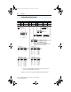
22B-UM001.book Page 2 Wednesday, January 22, 2014 11:04 AM A-2 Supplemental Drive Information Specifications Drive Ratings Catalog Number(1) Output Ratings Input Ratings Branch Circuit Protection Min. Enclosure 140M Motor Voltage kW (HP) Amps Range kVA Amps Fuses Protectors(3) (4) Contactors Volume(5) (in.3) 100 - 120V AC (±10%) – 1-Phase Input, 0 - 230V 3-Phase Output 22B-V2P3x104 0.4 (0.5) 2.3 90-132 1.15 9.0 15 140M-C2E-C16 100-C12 1655 22B-V5P0x104 0.75 (1.0) 5.0 90-132 2.45 20.
22B-UM001.book Page 3 Wednesday, January 22, 2014 11:04 AM Supplemental Drive Information (4) (5) A-3 Manual Self-Protected (Type E) Combination Motor Controller, UL listed for 208 Wye or Delta, 240 Wye or Delta, 480Y/277 or 600Y/347. Not UL listed for use on 480V or 600V Delta/Delta, corner ground, or high-resistance ground systems.
22B-UM001.
22B-UM001.book Page 5 Wednesday, January 22, 2014 11:04 AM Supplemental Drive Information A-5 PowerFlex 40 Estimated Watts Loss (Rated Load, Speed & PWM) Voltage 100–120V 200–240V 380–480V 460–600V kW (HP) 0.4 (0.5) 0.75 (1.0) 1.1 (1.5) 0.4 (0.5) 0.75 (1.0) 1.1 (2.0) 2.2 (3.0) 3.7 (5.0) 5.5 (7.5) 7.5 (10) 0.4 (0.5) 0.75 (1.0) 1.1 (2.0) 2.2 (3.0) 3.7 (5.0) 5.5 (7.5) 7.5 (10) 11 (15) 0.75 (1.0) 1.5 (2.0) 2.2 (3.0) 4.0 (5.0) 5.5 (7.5) 7.
22B-UM001.book Page 6 Wednesday, January 22, 2014 11:04 AM A-6 Supplemental Drive Information Notes: PowerFlex 40 Adjustable Frequency AC Drive FRN 1.xx - 6.
22B-UM001.book Page 1 Wednesday, January 22, 2014 11:04 AM Appendix B Accessories and Dimensions Product Selection Table B.A Catalog Number Description 22B Drive A 1P5 N 1 1 4 Voltage Rating Rating Enclosure HIM Emission Class Type Table B.B PowerFlex 40 Drives IP20 Flange IP20, NEMA/UL Type Open Mount(1) Drive Ratings IP66, NEMA/UL Type 4X Input Voltage kW HP Output Current Catalog Number Frame Size Catalog Number Catalog Number 120V 50/60 Hz 1-Phase No Filter 0.4 0.5 2.
22B-UM001.book Page 2 Wednesday, January 22, 2014 11:04 AM B-2 Accessories and Dimensions Table B.C Dynamic Brake Modules Drive Ratings Input Voltage kW HP Minimum Resistance Ω Catalog Number (1) (2) 120V 50/60 Hz 1-Phase 0.4 0.5 48 AK-R2-091P500 0.75 1.0 48 AK-R2-091P500 1.1 1.5 48 AK-R2-091P500 0.4 0.5 48 AK-R2-091P500 0.75 1.0 48 AK-R2-091P500 1.5 2.0 48 AK-R2-091P500 2.2 3.0 32 AK-R2-047P500 0.4 0.5 48 AK-R2-091P500 0.75 1.0 48 AK-R2-091P500 1.5 2.
22B-UM001.book Page 3 Wednesday, January 22, 2014 11:04 AM Accessories and Dimensions B-3 Table B.D Bulletin 1321-3R Series Line Reactors Input Voltage kW HP 240V 50/60 Hz 0.4 0.5 3-Phase 0.75 1.0 Maximum Fundamental Continuous Inductance Watts Amps Amps mh Loss 4 6 12.0 21 W 1321-3R4-D 8 12 3.0 29 W 1321-3R8-B 1.5 2.0 8 12 1.5 19.5 W 1321-3R8-A 2.2 3.0 12 18 1.25 26 W 1321-3R12-A 3.7 5.0 18 27 0.8 36 W 1321-3R18-A 5.5 7.5 25 37.5 0.5 48 W 1321-3R25-A 7.5 10.
22B-UM001.book Page 4 Wednesday, January 22, 2014 11:04 AM B-4 Accessories and Dimensions Table B.F EMC Line Filters Drive Ratings S Type Filter Catalog Number (1) L Type Filter Catalog Number (4) 0.5 – 22-RF018-BL 1.0 – 22-RF018-BL 1.5 – 22-RF018-BL 0.4 0.5 (2) 22-RF018-BL 0.75 1.0 (2) 22-RF018-BL 1.5 2.0 (2) 22-RF018-BL 2.2 3.0 (2) 22-RF025-CL 0.4 0.5 22-RF021-BS(3) 22-RF021-BL 0.75 1.0 22-RF021-BS(3) 22-RF021-BL 1.5 2.0 22-RF021-BS(3) 22-RF021-BL 2.2 3.
22B-UM001.book Page 5 Wednesday, January 22, 2014 11:04 AM Accessories and Dimensions B-5 Table B.G Human Interface Module (HIM) Option Kits and Accessories Item Description Catalog Number LCD Display, Remote Panel Mount Digital speed control CopyCat capable IP66 (NEMA Type 4X/12) indoor use only Includes 2.9 meter cable 22-HIM-C2S LCD Display, Remote Panel Mount Digital speed control CopyCat capable IP66 (NEMA Type 4X/12) indoor use only Includes 2.
22B-UM001.book Page 6 Wednesday, January 22, 2014 11:04 AM B-6 Accessories and Dimensions Table B.I Communication Option Kits and Accessories Item Description Catalog Number Communication Adapters Embedded communication options for use with the PowerFlex 4-Class drives. Requires a Communication Adapter Cover (IP20, NEMA/UL Type 1 only.
22B-UM001.book Page 7 Wednesday, January 22, 2014 11:04 AM Accessories and Dimensions B-7 Product Dimensions Table B.J PowerFlex 40 Frames – Ratings are in kW and (HP) Frame B 120V AC – 1-Phase 240V AC – 1-Phase 240V AC – 3-Phase 0.4 (0.5) 0.75 (1.0) 1.1 (1.5) 0.4 (0.5) 0.75 (1.0) 1.5 (2.0) 2.2 (3.0) 0.4 (0.5) 0.75 (1.0) 1.5 (2.0) 5.5 (7.5) 7.5 (10.0) C(1) 2.2 (3.0) 3.7 (5.0) 0.4 (0.5) 0.75 (1.0) 1.5 (2.0) 5.5 (7.5) 7.5 (10.0) 600V AC – 3-Phase 2.2 (3.0) 4.0 (5.0) 0.75 (1.0) 1.5 (2.0) 11.
22B-UM001.book Page 8 Wednesday, January 22, 2014 11:04 AM B-8 Accessories and Dimensions Figure B.3 IP30, NEMA/UL Type 1 Option Kit with Communication Option – Dimensions are in millimeters and (inches) 25.0 (0.98) 77.5 (3.05) 50.0 (1.97) 22.5 (0.89) ∅ 22.2 (0.87) 134.3 (5.29) 105.3 (4.15) 76.3 (3.00) 64.0 (2.52) Frame B - 22-JBCB 25.0 (0.98) 108.7 (4.28) 92.2 (3.63) 69.2 (2.72) 45.7 (1.80) 22.2 (0.87) ∅ 28.5 (1.12) ∅ 22.2 (0.87) 179.8 (7.08) 144.8 (5.70) 109.8 (4.32) 60.0 (2.
22B-UM001.book Page 9 Wednesday, January 22, 2014 11:04 AM Accessories and Dimensions B-9 Figure B.4 PowerFlex 40 Flange Mount Drives – Dimensions are in millimeters and (inches) 244 (9.61) 94.3 (3.71) 214 (8.43) 63.1 (2.48) 250 (9.84) Frame B 130.3 (5.13) 300 (11.81) 105.8 (4.17) 138.2 (5.44) 325 (12.8) 22B-CCC Frame C PowerFlex 40 Adjustable Frequency AC Drive FRN 1.xx - 6.
22B-UM001.book Page 10 Wednesday, January 22, 2014 11:04 AM B-10 Accessories and Dimensions Figure B.5 PowerFlex 40 Flange Mount Cutout Dimensions – Dimensions are in millimeters and (inches) 145 (5.71) 6.5 (0.26) 23.5 (0.93) 197 (7.76) 210 (8.27) 225 (8.86) 98.5 (3.88) 5.3 (0.21) 14 (0.55) 31 (1.22) 49 (1.93) 98 (3.86) 7.5 (0.30) 160 (6.30) Frame B 5.3 (0.21) 164 (6.46) 8 (0.31) 307.5 (12.11) 230.6 (9.08) 291.5 (11.48) 153.8 (6.06) 76.9 (3.03) 90 (3.54) 180 (7.
22B-UM001.book Page 11 Wednesday, January 22, 2014 11:04 AM Accessories and Dimensions B-11 Figure B.6 PowerFlex 40 Replacement Plate Drive Dimensions – Dimensions are in millimeters and (inches) 112 (4.41) 125 (4.92) 80 (3.15) 88 (3.46) 9.5 (0.37) 192 (7.56) 180 (7.09) 204 (8.03) 96 (3.78) 5.3 (0.21) 100 (3.94) Frame B 142 (5.59) 155 (6.10) 123.5 (4.86) 80 (3.15) 98.5 (3.88) 9.5 (0.37) 272 (10.71) 284 (11.18) 260 (10.24) 136 (5.35) 130 (5.12) 5.3 (0.
22B-UM001.book Page 12 Wednesday, January 22, 2014 11:04 AM B-12 Accessories and Dimensions Figure B.7 IP66, NEMA Type/UL Type 4X – Dimensions are in millimeters and (inches) Weights are in kilograms and (pounds). 165 (6.50) 146 (5.75) 6.5 (0.26) 46 (1.81) 23 (0.91) 270 (10.63) 198 (7.80) 253 (9.96) 28 (1.10) 124 (4.88) 89 (3.50) 22 (0.87) 82.5 (3.25) Weight 5.2 (11.5) PowerFlex 40 Adjustable Frequency AC Drive FRN 1.xx - 6.
22B-UM001.book Page 13 Wednesday, January 22, 2014 11:04 AM Accessories and Dimensions B-13 Figure B.8 Dynamic Brake Modules – Dimensions are in millimeters and (inches). Weights are in kilograms and (pounds). Frame A Frame B 30.0 (1.18) 60.0 (2.36) 31.0 (1.22) 59.0 (2.32) C US C US 17.0 (0.67) 61.0 (2.40) 335.0 (13.19) 386.0 (15.20) 405.0 (15.94) AUTOMATION ROCKWELL 316.0 (12.44) ROCKWELL AUTOMATION SURFACES MAY BE 13.0 (0.
22B-UM001.book Page 14 Wednesday, January 22, 2014 11:04 AM B-14 Accessories and Dimensions Figure B.10 Bulletin 1321-3R Series Line Reactors – Dimensions are in millimeters and (inches). Weights are in kilograms and (pounds). A B E D C Catalog Number A B C D E Weight 1321-3R2-A 112 (4.40) 104 (4.10) 70 (2.75) 50 (1.98) 37 (1.44) 1.8 (4) 1321-3R2-B 112 (4.40) 104 (4.10) 70 (2.75) 50 (1.98) 37 (1.44) 1.8 (4) 1321-3R4-A 112 (4.40) 104 (4.10) 76 (3.00) 50 (1.98) 37 (1.44) 1.
22B-UM001.book Page 15 Wednesday, January 22, 2014 11:04 AM Accessories and Dimensions B-15 Figure B.11 Frame B EMC Line Filters – Dimensions are in millimeters and (inches) Catalog Numbers: 22-RF8P0-BL, 22-RF012-BS, -BL (Series B); 22-RF018-BS; 22-RF021-BS, -BL 29.8 (1.17) 50 (1.97) 100 78 (3.94) (3.07) 217 (8.54) 229 (9.02) 216 (8.50) 17.8 (0.70) 24.0 (0.94) 5.5 (0.22) PowerFlex 40 Adjustable Frequency AC Drive FRN 1.xx - 6.
22B-UM001.book Page 16 Wednesday, January 22, 2014 11:04 AM B-16 Accessories and Dimensions Figure B.12 Frame C EMC Line Filters – Dimensions are in millimeters and (inches) Catalog Numbers: 22-RF018-CS, -CL; 22-RF025-CL; 22-RF026-CS, -CL; 22-RF034-CS, -CL 32 (1.26) 60 (2.36) 130 90 (5.12) (3.54) 297 (11.69) 309 (12.17) 297 (11.69) 17 (0.67) 30 (1.18) PowerFlex 40 Adjustable Frequency AC Drive FRN 1.xx - 6.xx User Manual Publication 22B-UM001H-EN-E 5.5 (0.
22B-UM001.book Page 17 Wednesday, January 22, 2014 11:04 AM Accessories and Dimensions B-17 Figure B.13 Remote (Panel Mount) Small HIM – Dimensions are in millimeters and (inches) Catalog Number: 22-HIM-C2S 25 (0.98) 93 (3.66) 180 (7.09) 2m 67 (2.64) 60 (2.36) 154 (6.06) 19.1 (0.75) 77 (3.03) 4.8 (0.19) 23.5 (0.93) PowerFlex 40 Adjustable Frequency AC Drive FRN 1.xx - 6.
22B-UM001.book Page 18 Wednesday, January 22, 2014 11:04 AM B-18 Accessories and Dimensions Figure B.14 NEMA Type 1 Bezel – Dimensions are in millimeters and (inches) Catalog Number: 22-HIM-B1 93 (3.66) 25.2 (0.99) 11.1 (0.44) 180 (7.09) 2m 67 (2.64) 60 (2.36) 154 (6.06) 4.8 (0.19) 77 (3.03) 19.1 (0.75) 23.5 (0.93) PowerFlex 40 Adjustable Frequency AC Drive FRN 1.xx - 6.
22B-UM001.book Page 1 Wednesday, January 22, 2014 11:04 AM Appendix C RS485 (DSI) Protocol PowerFlex 40 drives support the RS485 (DSI) protocol to allow efficient operation with Rockwell Automation peripherals. In addition, some Modbus functions are supported to allow simple networking. PowerFlex 40 drives can be multi-dropped on an RS485 network using Modbus protocol in RTU mode. Controller For information regarding DeviceNet or other communication protocols, refer to the appropriate user manual.
22B-UM001.book Page 2 Wednesday, January 22, 2014 11:04 AM C-2 RS485 (DSI) Protocol Only pins 4 and 5 on the RJ45 plug should be wired. The other pins on the PowerFlex 40 RJ45 socket must not be connected because they contain power, etc. for other Rockwell Automation peripheral devices. Wiring terminations on the master controller will vary depending on the master controller used and “TxRxD+” and “TxRxD-” are shown for illustration purposes only.
22B-UM001.book Page 3 Wednesday, January 22, 2014 11:04 AM RS485 (DSI) Protocol C-3 Parameter Configuration The following PowerFlex 40 parameters are used to configure the drive to operate on a network. Parameter Details Reference P036 [Start Source] Set to 5 “RS485 (DSI) Port” if Start is controlled from the network. Page 3-10 P038 [Speed Reference] Set to 5 “RS485 (DSI) Port” if the Speed Reference is controlled from the network.
22B-UM001.book Page 4 Wednesday, January 22, 2014 11:04 AM C-4 RS485 (DSI) Protocol Writing (06) Logic Command Data The PowerFlex 40 drive can be controlled via the network by sending Function Code 06 writes to register address 8192 (Logic Command). P036 [Start Source] must be set to 5 “RS485 (DSI) Port” in order to accept the commands. In addition to being written, register address 8192 can be read using Function Code 03.
22B-UM001.book Page 5 Wednesday, January 22, 2014 11:04 AM RS485 (DSI) Protocol C-5 Writing (06) Reference The Speed Reference to a PowerFlex 40 drive can be controlled via the network by sending Function Code 06 writes to register address 8193 (Reference). P038 [Speed Reference] must be set to 5 “RS485 (DSI) Port” in order to accept the Speed Reference. In addition to being written, register address 8193 can be read using Function Code 03.
22B-UM001.book Page 6 Wednesday, January 22, 2014 11:04 AM C-6 RS485 (DSI) Protocol Reading (03) Feedback The Feedback (Output Frequency) from the PowerFlex 40 drive can be read via the network by sending Function Code 03 reads to register address 8451 (Feedback). Feedback(2) Address (Decimal) 8451 (2) Description A xxx.x decimal value where the decimal point is fixed. For example, a decimal “123” equals 12.3 Hz and “300” equals 30.0 Hz.
22B-UM001.book Page 7 Wednesday, January 22, 2014 11:04 AM RS485 (DSI) Protocol C-7 Reading (03) and Writing (06) Drive Parameters To access drive parameters, the Modbus register address equals the parameter number. For example, a decimal “1” is used to address Parameter d001 [Output Freq] and decimal “39” is used to address Parameter P039 [Accel Time 1]. Additional Information Refer to http://www.ab.com/drives/ for additional information. PowerFlex 40 Adjustable Frequency AC Drive FRN 1.xx - 6.
22B-UM001.book Page 8 Wednesday, January 22, 2014 11:04 AM C-8 RS485 (DSI) Protocol Notes: PowerFlex 40 Adjustable Frequency AC Drive FRN 1.xx - 6.
22B-UM001.book Page 1 Wednesday, January 22, 2014 11:04 AM Appendix D RJ45 DSI Splitter Cable The PowerFlex 40 drive provides a RJ45 port to allow the connection of a single peripheral device. The RJ45 DSI Splitter Cable can be used to connect a second DSI peripheral device to the drive. Connectivity Guidelines ! ATTENTION: Risk of injury or equipment damage exists. The peripherals may not perform as intended if these Connectivity Guidelines are not followed.
22B-UM001.book Page 2 Wednesday, January 22, 2014 11:04 AM D-2 RJ45 DSI Splitter Cable DSI Cable Accessories PIN 1 S Slave Port M RJ45 Splitter Cable – Catalog Number: AK-U0-RJ45-SC1 Master Port PIN 8 RJ45 Two-Position Terminal Block Adapter – Catalog Number: AK-U0-RJ45-TB2P TB2 (PIN 5) PIN 8 TB1 (PIN 4) PIN 1 RJ45 Adapter with Integrated Termination Resistor – Catalog Number: AK-U0-RJ45-TR1 PIN 8 PIN 1 PowerFlex 40 Adjustable Frequency AC Drive FRN 1.xx - 6.
22B-UM001.
22B-UM001.
22B-UM001.book Page 1 Wednesday, January 22, 2014 11:04 AM Appendix E StepLogic™, Basic Logic and Timer/Counter Functions Four PowerFlex 40 logic functions provide the capability to program simple logic functions without a separate controller. • StepLogic Function Steps through up to eight preset speeds based on programmed logic. Programmed logic can include conditions that need to be met from digital inputs programmed as “Logic In1” and “Logic In2” before stepping from one preset speed to the next.
22B-UM001.book Page 2 Wednesday, January 22, 2014 11:04 AM E-2 StepLogic™, Basic Logic and Timer/Counter Functions StepLogic Using Timed Steps To activate this function, set parameter P038 [Speed Reference] to 6 “Stp Logic”. Three parameters are used to configure the logic, speed reference and time for each step. • Logic is defined using parameters A140-A147 [Stp Logic x]. • Preset Speeds are set with parameters A070-A077 [Preset Freq x].
22B-UM001.book Page 3 Wednesday, January 22, 2014 11:04 AM StepLogic™, Basic Logic and Timer/Counter Functions E-3 StepLogic Using Basic Logic Functions Digital input and digital output parameters can be configured to use logic to transition to the next step. Logic In1 and Logic In2 are defined by programming parameters A051-A054 [Digital Inx Sel] to option 23 “Logic In1” or option 24 “Logic In2”. Example • Run at Step 0. • Transition to Step 1 when Logic In1 is true.
22B-UM001.book Page 4 Wednesday, January 22, 2014 11:04 AM E-4 StepLogic™, Basic Logic and Timer/Counter Functions Timer Function Digital inputs and outputs control the timer function and are configured with parameters A051-A054 [Digital Inx Sel] set to 18 “Timer Start” and 20 “Reset Timer”. Digital outputs (relay and opto type) define a preset level and indicate when the level is reached.
22B-UM001.book Page 5 Wednesday, January 22, 2014 11:04 AM StepLogic™, Basic Logic and Timer/Counter Functions E-5 Output Frequency Start Relay Out Photo Eye Digital In1 Counter In Digital In2 Reset Counter Limit Switch Note that a “Reset Timer” input is not required for this example since the “Timer Start” input both clears and starts the timer. PowerFlex 40 Adjustable Frequency AC Drive FRN 1.xx - 6.
22B-UM001.book Page 6 Wednesday, January 22, 2014 11:04 AM E-6 StepLogic™, Basic Logic and Timer/Counter Functions Counter Function Digital inputs and outputs control the counter function and are configured with parameters A051-A054 [Digital Inx Sel] set to 19 “Counter In” and 21 “Reset Counter”. Digital outputs (relay and opto type) define a preset level and indicate when the level is reached.
22B-UM001.book Page 7 Wednesday, January 22, 2014 11:04 AM StepLogic™, Basic Logic and Timer/Counter Functions E-7 StepLogic Parameters Table E.A Code Descriptions for Parameters A140-A147 Digit 3 Digit 2 Digit 1 Digit 0 0 0 F 1 Table E.B Digit 3 – Defines the action during the step currently executing.
22B-UM001.book Page 8 Wednesday, January 22, 2014 11:04 AM E-8 StepLogic™, Basic Logic and Timer/Counter Functions Table E.D Digit 1 – Defines what logic must be met to jump to a step other than the very next step. Setting Description Logic 0 Skip Step (jump immediately) SKIP 1 Step based on the time programmed in the respective [Stp Logic Time x] TIMED parameter.
22B-UM001.book Page 1 Wednesday, January 22, 2014 11:04 AM Appendix F PID Set Up PID Loop The PowerFlex 40 has a built-in PID (proportional, integral, differential) control loop. The PID loop is used to maintain a process feedback (such as pressure, flow or tension) at a desired set point. The PID loop works by subtracting the PID feedback from a reference and generating an error value. The PID loop reacts to the error, based on the PID Gains, and outputs a frequency to try to reduce the error value to 0.
22B-UM001.book Page 2 Wednesday, January 22, 2014 11:04 AM F-2 PID Set Up Exclusive Control In Exclusive Control, the Speed Reference becomes 0, and the PID Output becomes the entire Freq Command. Exclusive Control is used when A132 [PID Ref Sel] is set to option 1, 2, 3 or 4. This configuration does not require a master reference, only a desired set point, such as a flow rate for a pump.
22B-UM001.book Page 3 Wednesday, January 22, 2014 11:04 AM PID Set Up F-3 Trim Control In Trim Control, the PID Output is added to the Speed Reference. In Trim mode, the output of the PID loop bypasses the accel/decel ramp as shown. Trim Control is used when A132 [PID Ref Sel] is set to option 5, 6, 7 or 8.
22B-UM001.book Page 4 Wednesday, January 22, 2014 11:04 AM F-4 PID Set Up PID Reference and Feedback Parameter A132 [PID Ref Sel] is used to enable the PID mode (A132 ¦ 0 “PID Disabled”) and to select the source of the PID Reference. If A132 [PID Ref Sel] is not set to 0 “PID Disabled”, PID can still be disabled by select programmable digital input options (parameters A051-A054) such as “Jog”, “Local” or “PID Disable”. Table F.
22B-UM001.book Page 5 Wednesday, January 22, 2014 11:04 AM PID Set Up F-5 Analog PID Reference Signals Parameters A110 [Anlg In 0-10V Lo] and A111 [Anlg In 0-10V Hi] are used to scale or invert an analog PID Reference. Important: Firmware version FRN 2.xx also allows PID Feedback scaling from an analog input. Examples Scale Function For a 0-5 volt signal, the following parameter settings are used so that a 0 volt signal = 0% PID Reference and a 5 volt signal = 100% PID Reference.
22B-UM001.book Page 6 Wednesday, January 22, 2014 11:04 AM F-6 PID Set Up Invert Function For a 4-20mA signal, the following parameter settings are used so that a 20mA signal = 0% PID Reference and a 4mA signal = 100% PID Reference. • A112 [Anlg In 4-20mA Lo] = 100.0% • A113 [Anlg In 4-20mA Hi] = 0.
22B-UM001.book Page 7 Wednesday, January 22, 2014 11:04 AM PID Set Up F-7 PID Preload The value set in A139 [PID Preload], in Hertz, will be pre-loaded into the integral component of the PID at any start or enable. This will cause the drive’s frequency command to initially jump to that preload frequency, and the PID loop starts regulating from there.
22B-UM001.book Page 8 Wednesday, January 22, 2014 11:04 AM F-8 PID Set Up PID Gains The proportional, integral, and differential gains make up the PID regulator. • A134 [PID Prop Gain] The proportional gain (unitless) affects how the regulator reacts to the magnitude of the error. The proportional component of the PID regulator outputs a speed command proportional to the PID error.
22B-UM001.book Page 9 Wednesday, January 22, 2014 11:04 AM PID Set Up F-9 Guidelines for Adjusting the PID Gains 1. Adjust the proportional gain. During this step it may be desirable to disable the integral gain and differential gain by setting them to 0. After a step change in the PID Feedback: – If the response is too slow increase A134 [PID Prop Gain]. – If the response is too quick and/or unstable (see Figure F.1), decrease A134 [PID Prop Gain].
22B-UM001.book Page 10 Wednesday, January 22, 2014 11:04 AM F-10 PID Set Up The following figures show some typical responses of the PID loop at different points during adjustment of the PID Gains. Figure F.1 Unstable PID Reference PID Feedback Time Figure F.2 Slow Response – Over Damped PID Reference PID Feedback Time Figure F.3 Oscillation – Under Damped PID Reference PID Feedback Time Figure F.
22B-UM001.
22B-UM001.
22B-UM001.
22B-UM001.book Page 4 Wednesday, January 22, 2014 11:04 AM Index-4 Notes: PowerFlex 40 Adjustable Frequency AC Drive FRN 1.xx - 6.
22B-UM001.
22B-UM001.book Page 2 Wednesday, January 22, 2014 11:04 AM U.S. Allen-Bradley Drives Technical Support Tel: (1) 262.512.8176, Fax: (1) 262.512.2222, Email: support@drives.ra.rockwell.com, Online: www.ab.com/support/abdrives www.rockwellautomation.com Power, Control and Information Solutions Headquarters Americas: Rockwell Automation, 1201 South Second Street, Milwaukee, WI 53204-2496 USA,Tel: (1) 414.382.2000, Fax: (1) 414.382.