
Owner's manual

SLC Example Ladder Program F-3
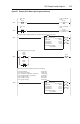
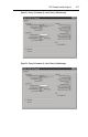
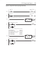
Figure F.1 Example SLC Ladder Logic Program (Continued)
0005
B3:0
4
Fwd / Rev
SS
N7:20
4
Logic Command
FWD
0006
B3:0
4
Fwd / Rev
SS
N7:20
5
Logic Command
REV
Write the Logic Command (N182:192) and Reference (N182:193) to the drive.
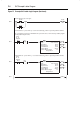
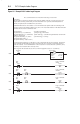
0007
EN
DN
ER
MSG
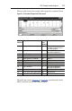
Read/Write Message
Type Peer-To-Peer
Read/Write Write
Target Device PLC5
Local/Remote Local
Control Block N9:0
Control Block Length 14
Setup Screen
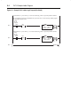
MSG
Starts the message cycle over again.
0008
N9:0
13
MSG
Done
N9:0
12
MSG
Error
U
N9:0
15
Reads a block of data (starting at N183:198) containing:
N7:10 Logic Status (N183:198)
N7:11 Drive Error Code (N183:199)
N7:12 Frequency Command (= Reference) (N183:200)
N7:13 Output Frequency (Feedback) (N183:201)
N7:14 Output Current (N183:202)
N7:15 DC Bus Voltage (N183:203)
N7:16 Output Voltage (N183:204)
0009
EN
DN
ER
MSG
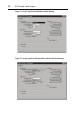
Read/Write Message
Type Peer-To-Peer
Read/Write Read
Target Device PLC5
Local/Remote Local
Control Block N9:40
Control Block Length 14
Setup Screen
MSG