
Owner's manual


MicroLogix 1200/1500 Example Ladder Program E-5
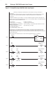
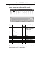
The data table used by the example ladder program is explained below:
Figure E.2 MicroLogix 1200/1500 Ladder Example Data Table Values
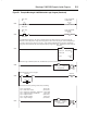
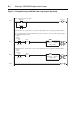
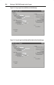
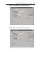
The following screens (Figure E.3 to Figure E.6) provide details of the
MSG instructions used in the ladder example:
N7:
Address
Name Example
Value
(decimal)
Example Value Description
0 Constant “0” 0 Fixed to “0” and used to clear
read data on the first scan of
the ladder program
10 Logic Status 1807 See Logic Status bit
descriptions (Appendix I)
11 Drive Error Code 0 No errors
12 Commanded Frequency 336 33.6 Hz
13 Output Frequency (feedback) 336 33.6 Hz
14 Output Current 1 0.01 A
15 DC Bus Voltage 3308 330.8 V
16 Output Voltage 1343 134.3 V
20 Logic Command 16 See Logic Command bit
descriptions (Appendix I)
21 Reference 336 33.6 Hz
30 Pr. 39 - [Accel Time 1] Write Value 100 10.0 Seconds
31 Pr. 39 - [Accel Time 1] Read Value 100 10.0 Seconds