
Owner's manual

4-4 Controlling PowerFlex 4 and 40 Drives with Allen-Bradley Controllers
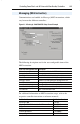
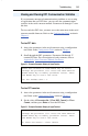
PowerFlex 4 and 40 control and status information, and parameters are
addressed using N: file addressing.
Logic Command/Reference
Logic Status/Feedback/Additional Monitor Data
The Logic Command and Logic Status bit definitions are described in
Appendix I.
Parameters
PowerFlex 4 and 40 parameters are addressed using Integer File N150:x,
where “x” equals the actual parameter number in the drive. For example:
N150:39 = Parameter 39 - [Accel Time 1]
Example ladder logic programs are provided for each type of controller
platform. Refer to the appropriate appendix:
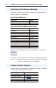
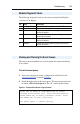
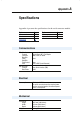
PowerFlex 4 and 40 Memory Addressing
Control Data Address
Logic Command N182:192
Reference N182:193
Monitor Data Address
Logic Status N183:198
Drive Error Code N183:199
Frequency Command N183:200
Output Frequency (Feedback) N183:201
Output Current N183:202
DC Bus Voltage N183:203
Output Voltage N183:204
Step # of Multi-Step Speed Operation N183:205
Step # of PLC Operation N183:206
Time of PLC Operation N183:207
Counter Value N183:208
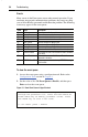
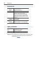
Example Controller Programs
Controller Type Example Ladder Logic Program
• MicroLogix 1000 See Appendix D
• MicroLogix 1200/1500 See Appendix E
• SLC See Appendix F
• PLC See Appendix G
• ControlLogix/CompactLogix See Appendix H