Serial Converter Module 22-SCM-232 FRN 2.
Important User Information Solid state equipment has operational characteristics differing from those of electromechanical equipment. “Safety Guidelines for the Application, Installation and Maintenance of Solid State Controls” (Publication SGI-1.1 available from your local Rockwell Automation Sales Office or online at http://www.ab.com/ manuals/gi) describes some important differences between solid state equipment and hard-wired electromechanical devices.
Summary of Changes This is the second release of the 22-SCM-232 serial converter module (FRN 2.xxx). Location Chapter 4 Chapter 5 Appendix D Appendix E Appendix F Appendix G Appendix H Appendix I Description of Changes Added (before old Chapter 4 - Troubleshooting) to describe how to use 22-SCM-232 module with Allen-Bradley controllers to control and read/ write data to PowerFlex® 4 and 40 drives. Was Chapter 4 - renumbered to 5. Added to describe MicroLogix 1000 example ladder program.
soc-2 Notes:
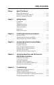
Table of Contents Preface About This Manual Related Documentation . . . . . . . . . . . . . . . . . . . . . . . . . . . . . P-1 Conventions Used in this Manual . . . . . . . . . . . . . . . . . . . . . P-1 Rockwell Automation Support. . . . . . . . . . . . . . . . . . . . . . . . P-2 Chapter 1 Getting Started Components . . . . . . . . . . . . . . . . . . . . . . . . . . . . . . . . . . . . . . Features . . . . . . . . . . . . . . . . . . . . . . . . . . . . . . . . . . . . . . . . .
ii Table of Contents Appendix A Specifications Communications . . . . . . . . . . . . . . . . . . . . . . . . . . . . . . . . . Electrical . . . . . . . . . . . . . . . . . . . . . . . . . . . . . . . . . . . . . . . Mechanical . . . . . . . . . . . . . . . . . . . . . . . . . . . . . . . . . . . . . . Environmental . . . . . . . . . . . . . . . . . . . . . . . . . . . . . . . . . . . Agency Certification . . . . . . . . . . . . . . . . . . . . . . . . . . . . . .
Preface About This Manual Read this preface to become familiar with the rest of the manual. Topic Related Documentation Conventions Used in this Manual Rockwell Automation Support Page P-1 P-1 P-2 Related Documentation For Information On: Refer to: Publication DF1 Protocol DF1 Protocol and Command Set Reference manual 1770-6.5.
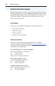
P-2 About This Manual Rockwell Automation Support Rockwell Automation, Inc. offers support services worldwide, with over 75 sales/support offices, over 500 authorized distributors, and over 250 authorized systems integrators located through the United States alone. In addition, Rockwell Automation, Inc. representatives are in every major country in the world. Local Support Contact your local Rockwell Automation, Inc. representative for: • Sales and order support. • Technical training.
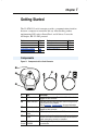
Chapter 1 Getting Started The 22-SCM-232 serial converter provides a communications interface between a computer or controller and any Allen-Bradley product implementing DSI, such as PowerFlex 4 and 40 drives. It uses the full-duplex, RS-232 DF1 protocol. Topic Components Features Compatible Products Required Equipment Page 1-1 1-2 1-2 1-3 Topic Safety Precautions Quick Start Modes of Operation Page 1-4 1-5 1-6 Components Figure 1.
1-2 Getting Started Features The 22-SCM-232 serial converter module features the following: • The serial converter module can connect to products implementing DSI such as PowerFlex 4 and 40 drives. • Provides a means for DriveExplorer (version 3.01 or higher) and DriveExecutive (version 1.01 or higher) software tools to access PowerFlex 4 and 40 drives. • Allows various Allen-Bradley controllers, from MicroLogix to ControlLogix, to control and read/write data to PowerFlex 4 and 40 drives.
Getting Started 1-3 Required Equipment Equipment Shipped with the Serial Converter Module When you unpack the serial converter module, verify that the package includes: ❑ ❑ ❑ ❑ ❑ One 22-SCM-232 Serial Converter Module One 1203-SFC serial cable One 22-RJ45CBL-C20 cable One DriveExplorer Lite CD This manual User-Supplied Equipment To configure the serial converter, you must use one of the following: ❑ ❑ ❑ ❑ DriveExplorer software (version 3.01 or higher). DriveExecutive software (version 1.01 or higher).
1-4 Getting Started Safety Precautions Please read the following safety precautions carefully. ! ! ! ATTENTION: Risk of injury or equipment damage exists. Only personnel familiar with drive and power products and the associated machinery should plan or implement the installation, start-up, configuration, and subsequent maintenance of the product using the serial converter module. Failure to comply may result in injury and/or equipment damage. ATTENTION: Risk of injury or equipment damage exists.
Getting Started 1-5 Quick Start This section is designed to help experienced users quickly start using the serial converter module. If you are unsure how to complete a step, refer to the referenced chapter. Step Action 1 Review the safety precautions for the serial converter module. 2 Install the serial converter module. Connect a 22-RJ45CBL-C20 cable to the serial converter module and the DSI drive. Then, connect a 1203-SFC serial cable to the serial converter module and a computer.
1-6 Getting Started Figure 1.4 Example Serial Connection to a Controller 22-RJ45CBL-C20 Cable 1203-SFC Cable DSI Host Serial Converter MicroLogix Modes of Operation Figure 1.5 Status Indicators on the Serial Converter Module ➊ ➋ ➌ AB The serial converter module uses three status indicators to report its operating status (Figure 1.5).
Chapter 2 Installing the Serial Converter Module Chapter 2 provides instructions for installing and removing the serial converter module. Topic Selecting Cables Installing the Serial Converter Module Removing the Serial Converter Module Page 2-1 2-2 2-3 Selecting Cables The following cables are all you should need to connect the serial converter module to a drive and a computer. Figure 2.1 Cables ➊ ➋ ➌ Number Description DSI cable to connect the serial converter module to ➊ the drive.
Installing the Serial Converter Module should be connected to the serial cable shield at the shell of the 9-pin sub-miniature D connector. Important: The DSI cable shield must be properly grounded in order to provide EMC protection. On the PowerFlex 4 and 40 drive that means that Pin 16 of the drive control terminal block must be connected to the drive earth ground terminal.
Installing the Serial Converter Module 2-3 Removing the Serial Converter Module ! ATTENTION: Risk of injury or equipment damage exists. If the serial converter module is transmitting control I/O to the drive (indicated by a solid green diamond LED), the drive may fault when you remove or reset the serial converter. Determine how your drive will respond before removing or resetting a connected serial converter module. 1.
2-4 Notes: Installing the Serial Converter Module
Chapter 3 Configuring the Serial Converter Module Chapter 3 provides instructions and information for configuring the serial converter module. Topic Configuration Tools Using DriveExplorer Using Terminal Emulation Software Setting the RS-232 Serial Port Rate Setting the Fault Action Resetting the Serial Converter Module Page 3-1 3-2 3-3 3-7 3-8 3-9 For a list of parameters, refer to Appendix B, Serial Converter Module Parameters. For definitions of terms in this chapter, refer to the Glossary.
3-2 Configuring the Serial Converter Module Using DriveExplorer With DriveExplorer software, you can edit parameters in both the serial converter module and the connected DSI-enabled drive. On PowerFlex 4/40 drives (or other DSI products), you can also edit parameters in any of the attached peripherals. DriveExplorer Lite is shipped with the serial converter module and is a free, limited-feature version of DriveExplorer.
Configuring the Serial Converter Module 3-3 Using Terminal Emulation Software This section provides detailed instructions on how to use terminal emulation software to access the serial converter module so that you can view and edit its parameters or view its event queue. A variety of terminal emulation programs can be used to establish a serial connection between a computer and the serial converter module.
3-4 Configuring the Serial Converter Module Figure 3.3 Connection Dialog Box 4. In the Name window, type any name (for example, converter), and then select any icon in the Icon box. 5. Click OK to display the Phone Number dialog box (see Figure 3.4). Figure 3.4 Phone Number Dialog Box 6. In the Connect Using window, select the communications port that you intend to use (usually Com1 or Com2). 7. Click OK to display the Properties dialog box. 8. Select the settings shown in Figure 3.5.
Configuring the Serial Converter Module 3-5 Figure 3.5 Properties Dialog Box 9. Click OK. A blank HyperTerminal workspace appears. 10. Select File > Properties to display the Properties dialog box. 11. Click the Settings tab (see Figure 3.6). Figure 3.6 Properties Dialog Box 12. Under Function, arrow, and ctrl keys act as, select Terminal keys.
3-6 Configuring the Serial Converter Module 13. In the Emulation window, select VT100. 14. Click OK to display the HyperTerminal workspace. TIP: Select File > Save to save the HyperTerminal configuration that you just created. In future connections, you can select the saved configuration and quickly connect to the serial converter module. 15. Press the Enter key until the main menu appears (see Figure 3.7). Figure 3.
Configuring the Serial Converter Module 3-7 Setting the RS-232 Serial Port Rate The serial port rate, sometimes called baud rate or DF1 rate, is the speed at which the computer and serial converter module communicate over RS-232. You can select a serial port rate of 9600, 19.2K, or 38.4K. The factory-default serial port rate is 9600. Important: If you change the serial port rate in the serial converter module, you must set your software to use the same serial port rate.
3-8 Configuring the Serial Converter Module Setting the Fault Action By default, when DF1 serial communications are disrupted (for example, a serial cable is disconnected) and control I/O is being transmitted, the serial converter module and connected drive respond by faulting. You can set a different response to communication disruptions using Parameter 04 - [Comm Flt Action]. ! ATTENTION: Risk of injury or equipment damage exists.
Configuring the Serial Converter Module 3-9 Resetting the Serial Converter Module Change to settings on some module parameters require that you reset the serial converter module before the new settings take effect. You can reset the module by cycling power to the module or by using Parameter 05 [Reset Module]. ! ATTENTION: Risk of injury or equipment damage exists.
3-10 Notes: Configuring the Serial Converter Module
Chapter 4 Controlling PowerFlex 4 and 40 Drives with Allen-Bradley Controllers Chapter 4 illustrates how to use the 22-SCM-232 serial converter with Allen-Bradley controllers to control and read/write data to PowerFlex 4 and 40 drives.
4-2 Controlling PowerFlex 4 and 40 Drives with Allen-Bradley Controllers Figure 4.1 Point-to-Point Example Drive Controller RS232 DF1 AB RS485 Modbus RTU 22-SCM-232 Serial Converter Figure 4.
Controlling PowerFlex 4 and 40 Drives with Allen-Bradley Controllers 4-3 Messaging (MSG Instruction) Communications are handled via Message (MSG) instructions, which vary between the different controllers. Figure 4.3 MicroLogix 1200/1500 MSG Setup Screen Example The following descriptions are for the user configurable items of the MSG instruction.
4-4 Controlling PowerFlex 4 and 40 Drives with Allen-Bradley Controllers PowerFlex 4 and 40 Memory Addressing PowerFlex 4 and 40 control and status information, and parameters are addressed using N: file addressing.
Chapter 5 Troubleshooting Chapter 5 provides information for troubleshooting potential problems with the serial converter module. Topic Understanding the Status Indicators Module Diagnostic Items Viewing and Clearing the Event Queue Viewing and Clearing DF1 Communication Statistics Troubleshooting Potential Problems Page 5-1 5-3 5-3 5-5 5-6 Understanding the Status Indicators The serial converter module has three status indicators to reports its operating status. See Figure 5.1. Figure 5.
5-2 Troubleshooting Diamond Status Indicator ! ATTENTION: Risk of injury or equipment damage exists. If the serial converter module is transmitting control I/O to the drive (indicated by a solid green diamond LED), the drive may fault when you remove or reset the module. Determine how your drive will respond before removing or resetting a serial converter module. Status Off Cause Serial converter module is not powered or in Flash programming mode.
Troubleshooting 5-3 Module Diagnostic Items The following diagnostic items can be accessed using DriveExplorer (version 3.01 or higher). No. 1 2 3 Name Field Flash Cnt Adapter Events Reference 4 Logic Command 5 Logic Status 6 Feedback Description Number of times the module has been Field Flashed. The number of events in the event queue. Current value of the Reference being transmitted to the drive by this module. Current value of the Logic Command being transmitted to the drive by this module.
5-4 Troubleshooting Events Many events in the Event queue occur under normal operation. If you encounter unexpected communications problems, the events may help you or Allen-Bradley personnel troubleshoot the problem.
Troubleshooting 5-5 Viewing and Clearing DF1 Communication Statistics If you encounter unexpected communications problems or are creating an application that uses DF1 data, you can view the communications statistics in the serial converter module. Parameters 06 through 17 store this data. To view and clear DF1 data, you must access the main menu in the serial converter module firmware. Refer to the Configuration Tools section in Chapter 3. To view DF1 data 1.
5-6 Troubleshooting Troubleshooting Potential Problems Description You are unable to establish a connection between your computer and the serial converter module. After changing the serial port rate, you are no longer able to communicate with the serial converter module and connected drive. Action • If the status indicators are off, connect the cables and apply power to the drive. • Configure your software and serial converter module to use the same COMM port and serial port rate (baud rate).
Appendix A Specifications Appendix A presents the specifications for the serial converter module. Topic Communications Electrical Mechanical Page A-1 A-1 A-1 Topic Environmental Agency Certification Page A-2 A-2 Communications RS-232 side Protocol Port Rate Data Bits Parity Stop Bits Flow Control Error DSI Host side Protocol Data Rates RS-232 Serial DF1, Full Duplex 9600, 19.2K, or 38.4K 8 None 1 None CRC or BCC (Auto-Detected) Drive Serial Interface (DSI) 19.
A-2 Specifications Environmental Temperature Operating Storage Relative Humidity Atmosphere Vibration Operating Non-Operating Shock Operating Non-Operating 0 to +50° C (32 to 122° F) -40 to +85° C (-40 to 185° F) 5 to 95% non-condensing Important: Serial converter module must not be installed in an area where the ambient atmosphere contains volatile or corrosive gas, vapors or dust.
Appendix B Serial Converter Module Parameters Appendix B provides information about the serial converter module parameters. Parameter List No. 01 02 03 04 Name and Description Details Default: [Adapter Cfg] Sets the operation of the serial converter module on Values: DSI. Leave at “Auto” (setting) when used with software tools. Important: Parameter 1 - [Adapter Cfg] must be set to “Auto” (default) for DriveExplorer to operate.
B-2 No. 05 Serial Converter Module Parameters Name and Description [Reset Module] No action if set to “Ready.” Resets the serial converter module if set to “Reset Module.” Restores the module to its factory-default settings if set to “Set Defaults.” This parameter is a command. It will be reset to “0 = Ready” after the command has been performed. ! 06 07 08 09 Type: 0 = Ready 0 = Ready 1 = Reset Module 2 = Set Defaults Read/Write ATTENTION: Risk of injury or equipment damage exists.
Serial Converter Module Parameters No. 14 15 16 Name and Description [NAK No Memory](1) Displays the number of NAKs sent by the serial converter module because it did not have sufficient memory to buffer the incoming messages. The module runs out of memory if a command has not completed and there is no place to save the new commands. [Duplicate Msgs](1) Displays the number of duplicate messages sent to the serial converter module.
B-4 Notes: Serial Converter Module Parameters
Appendix C Flash Updates Appendix C provides information on updating peripheral product firmware. Topic Preparing for a Flash Update Performing a Flash Update with HyperTerminal Troubleshooting Potential HyperTerminal Flash Problems Page C-1 C-2 C-3 Preparing for a Flash Update Please take the following precautions to ensure a successful Flash: • Obtain the new firmware version from Rockwell Automation, Inc. Save it to the hard drive of the computer.
C-2 Flash Updates Performing a Flash Update with HyperTerminal 1. In the main menu (Figure 3.7), press 3 to Update Flash program. The screen in Figure C.1 will immediately appear. Figure C.1 Flash Menu To update the Flash memory, you need a terminal program capable of downloading a binary file using the XMODEM protocol and a Flash update file from Rockwell Automation. When you press 'Y' to signal that you are ready to proceed, the terminal program will start displaying the letter 'C'.
Flash Updates C-3 6. In the Protocol box, select Xmodem. Figure C.2 Example Send File Dialog Box 7. Click Send. A dialog box appears and reports the progress of the download. When it is complete, the message “Operation Complete” appears. Important: Keep the device powered for 15 seconds after the operation has completed. 8. Press the Enter key to return to the main menu.
C-4 Flash Updates Performing a Flash Update with DriveExplorer DriveExplorer version 4.xx and higher can perform flash updates on DSI products that use flash memory, such as the 22-SCM-232 Serial Converter Module and 22-COMM-D DeviceNet adapter. A 22-SCM-232 (version 2.01 or higher) is required to perform the update. DriveExplorer utilizes the same files used by ControlFlash, which can be downloaded from www.ab.com/drives.
Flash Updates C-5 3. Confirm that this is what you want to do by clicking the FLASH button. 4. The following dialog boxes will display information about the progress of the flash.
C-6 Flash Updates 5. When the flash is completed, the “FLASH” button changes to “Close” and the “Cancel” button is grayed out. 6. DriveExplorer will prompt you to reconnect since the device may have changed its database because of the flash. Click “Yes” to reconnect.
Appendix D MicroLogix 1000 Example Ladder Program Appendix D provides information on a MicroLogix 1000 example ladder program.
D-2 MicroLogix 1000 Example Ladder Program Figure D.1 Example MicroLogix 1000 Ladder Logic Program MicroLogix 1000 communications to a PowerFlex 4/40 using a 22-SCM-232 Connection: The 22-SCM-232 connects to the front port on the MicroLogix 1000 by using a 1203-SNM Null Modem adapter and a 1761-CBL-AP00 programming cable. The RJ45 cable on the 22-SCM-232 conencts to the RJ45 port on the PowerFlex 4/40. The SCM provides both media (RS232 to RS485) and protocol (DF1 to Modbus RTU) conversions.
MicroLogix 1000 Example Ladder Program Figure D.1 Example MicroLogix 1000 Ladder Logic Program (Continued) 0002 This rung sets the timeout value for the second MSG instruction. MSG #2 Enable Error Done Time Out (EN) (ER) (DN) Timer N7:60 N7:60 N7:60 TON Timer On Delay 15 12 13 Timer T4:1 Time Base 0.01 Preset 200< Accum 0< MSG #2 Time Out Timer T4:1 DN 0003 This rung sets the timeout value for the third MSG instruction.
D-4 MicroLogix 1000 Example Ladder Program Figure D.1 Example MicroLogix 1000 Ladder Logic Program (Continued) Messages must be interlocked and queued to run one at a time.
MicroLogix 1000 Example Ladder Program D-5 Figure D.1 Example MicroLogix 1000 Ladder Logic Program (Continued) If a read is requested elsewhere in the user program (B3:0/1) and the previous MSG is complete, this MSG will read Parameter 39 - [Accel Time 1]. Uses N150:x addressing, where 'x' equals the parameter number. Pr. 39 Pr. 39 Read Write Done (DN) Request Request B3:0 B3:0 N7:70 0008 1 0 13 Error (ER) N7:70 12 Pr.
D-6 MicroLogix 1000 Example Ladder Program Figure D.1 Example MicroLogix 1000 Ladder Logic Program (Continued) This rung resets all MSG instructions when the last MSG instruction has completed. Since the Parameter 39 Write and Read MSG's are on demand and not continuous, the "last" MSG in the sequence can vary. The Write (B3:0/0) and Read (B3:0/1) requests are also reset. This prevents these MSG's from operating continuously while providing feedback to the user program that they have completed. Pr.
MicroLogix 1000 Example Ladder Program Figure D.1 Example MicroLogix 1000 Ladder Logic Program (Continued) Enable (EN) N7:60 U 15 Enable (EN) N7:70 U 15 Enable (EN) N7:80 U 15 Pr. 39 Write Request B3:0 U 0 Pr.
D-8 MicroLogix 1000 Example Ladder Program The data table used by the example ladder program is explained below: Figure D.2 MicroLogix 1000 Ladder Example Data Table Values N7: Name Address 0 10 11 12 13 14 15 16 20 21 30 31 Example Example Value Description Value (decimal) Constant “0” 0 Fixed to “0” and used to clear read data on the first scan of the ladder program Logic Status 1567 See Logic Status bit descriptions (Appendix I) Drive Error Code 0 No errors Commanded Frequency 222 22.
MicroLogix 1000 Example Ladder Program Figure D.3 Rung 5 Logic Command/Reference Write Message Figure D.
D-10 MicroLogix 1000 Example Ladder Program Figure D.5 Rung 7 Parameter 39 - [Accel Time 1] Write Message Figure D.
Appendix E MicroLogix 1200/1500 Example Ladder Program Appendix E provides information on a MicroLogix 1200/1500 example ladder program. The following ladder example demonstrates: • Writing Logic Command and Reference • Reading Logic Status, Feedback, and additional monitor data • Writing/reading Parameter 39 - [Accel Time 1] The example ladder program is for a MicroLogix 1500, but can also be applied to the MicroLogix 1200.
E-2 MicroLogix 1200/1500 Example Ladder Program Figure E.1 Example MicroLogix 1200/1500 Ladder Logic Program MicroLogix 1500 (LRP) communications to a PowerFlex 4/40 using a 22-SCM-232 Connection: The 22-SCM-232 connects directly to Channel 1 on the LRP (DB9 connector) and the RJ45 port on the PowerFlex 4/40. It provides both media (RS232 to RS485) and protocol (DF1 to Modbus RTU) conversions. Additional PF4/40 drives can be added.
MicroLogix 1200/1500 Example Ladder Program E-3 Figure E.1 Example MicroLogix 1200/1500 Ladder Logic Program (Continued) Fwd / Rev SS I:0 Logic Command FORWARD N7:20 4 Bul.1764 4 Fwd / Rev SS I:0 Logic Command REVERSE N7:20 4 Bul.1764 5 0005 0006 0007 For demonstration purposes, the value of analog POT0 on the LRP processor is used to generate the Reference. Since the pot has a range of 0-250 (equates to 0.0 to 25.0 Hz), the pot value is multiplied by 3 to provide a range of 0 to 750 (0.
E-4 MicroLogix 1200/1500 Example Ladder Program Figure E.1 Example MicroLogix 1200/1500 Ladder Logic Program (Continued) Starts the message cycle over again MG11:2 0011 DN MG11:2 U EN MG11:2 ER Writes Parameter 39 - [Accel Time 1]. Uses N150:x addressing, where 'x' equals the parameter number. 0012 0013 0014 Note: A parameter write causes an EEPROM write cycle on the drive. Do not develop a ladder program that will perform frequent writes. Write Pr.
MicroLogix 1200/1500 Example Ladder Program E-5 The data table used by the example ladder program is explained below: Figure E.2 MicroLogix 1200/1500 Ladder Example Data Table Values N7: Name Address 0 10 11 12 13 14 15 16 20 21 30 31 Example Example Value Description Value (decimal) Constant “0” 0 Fixed to “0” and used to clear read data on the first scan of the ladder program Logic Status 1807 See Logic Status bit descriptions (Appendix I) Drive Error Code 0 No errors Commanded Frequency 336 33.
E-6 MicroLogix 1200/1500 Example Ladder Program Figure E.3 Rung 8 Logic Command/Reference Write Message Figure E.
MicroLogix 1200/1500 Example Ladder Program Figure E.5 Rung 12 Parameter 39 - [Accel Time 1] Write Message Figure E.
E-8 Notes: MicroLogix 1200/1500 Example Ladder Program
Appendix F SLC Example Ladder Program Appendix F provides information on an SLC example ladder program.
F-2 SLC Example Ladder Program Figure F.1 Example SLC Ladder Logic Program SLC 5/03 communications to a PowerFlex 4/40 using a 22-SCM-232 Connection: The 22-SCM-232 connects directly to Channel 0 on the processor (DB9 connector) and the RJ45 port on the PowerFlex 4/40. It provides both media (RS232 to RS485) and protocol (DF1 to Modbus RTU) conversions. Additional PF4/40 drives can be added. Use one AK-U0-RJ45-SC1 Splitter Cable for connecting to the first drive, and one AK-U0-RJ45-TB2P for every drive.
SLC Example Ladder Program F-3 Figure F.1 Example SLC Ladder Logic Program (Continued) Fwd / Rev SS B3:0 Logic Command FWD N7:20 0005 4 4 Fwd / Rev SS B3:0 Logic Command REV N7:20 4 5 0006 0007 Write the Logic Command (N182:192) and Reference (N182:193) to the drive. MSG Read/Write Message Type Peer-To-Peer Read/Write Write Target Device PLC5 Local/Remote Local Control Block N9:0 Control Block Length 14 Setup Screen Starts the message cycle over again.
F-4 SLC Example Ladder Program Figure F.1 Example SLC Ladder Logic Program (Continued) Starts the message cycle over again. N9:40 0010 13 N9:40 U 15 N9:40 12 Write Parameter 39 - [Accel Time 1]. Uses N150:x addressing, where 'x' equals the parameter number. 0011 0012 0013 Note: A parameter write causes an EEPROM write cycle on the drive. Do not develop a ladder program that will perform frequent writes. Write Pr.
SLC Example Ladder Program F-5 The data table used by the example ladder program is explained below: Figure F.2 SLC Ladder Example Data Table Values N7: Name Address 0 10 11 12 13 14 15 16 20 21 30 31 Example Example Value Description Value (decimal) Constant “0” 0 Fixed to “0” and used to clear read data on the first scan of the ladder program Logic Status 1807 See Logic Status bit descriptions (Appendix I) Drive Error Code 0 No errors Commanded Frequency 300 30.0 Hz Output Frequency (feedback) 300 30.
F-6 SLC Example Ladder Program Figure F.3 Rung 7 Logic Command/Reference Write Message Figure F.
SLC Example Ladder Program Figure F.5 Rung 11 Parameter 39 - [Accel Time 1] Write Message Figure F.
F-8 Notes: SLC Example Ladder Program
Appendix G PLC-5 Example Ladder Program Appendix G provides information on a PLC-5 example ladder program.
G-2 PLC-5 Example Ladder Program Figure G.1 Example PLC-5 Ladder Logic Program PLC-5 communications to a PowerFlex 4/40 using a 22-SCM-232 Connection: The 22-SCM-232 connects to Channel 0 on the processor (DB25 connector) via a 3rd party 9-to-25 pin adapter (Male-to-Male), and the RJ45 port on the PowerFlex 4/40. It provides both media (RS232 to RS485) and protocol (DF1 to Modbus RTU) conversions. Additional PF4/40 drives can be added.
PLC-5 Example Ladder Program G-3 Figure G.1 Example PLC-5 Ladder Logic Program (Continued) Fwd / Rev SS I:001 Logic Command FWD N7:20 0005 4 4 Fwd / Rev SS I:001 Logic Command REV N7:20 0006 5 4 0007 Write the Logic Command (N182:192) and Reference (N182:193) to the drive. MSG Read/Write Message Control MG10:0 Setup Screen Starts the message cycle over again.
G-4 PLC-5 Example Ladder Program Figure G.1 Example PLC-5 Ladder Logic Program (Continued) Write Parameter 39 - [Accel Time 1]. Uses N150:x addressing, where 'x' equals the parameter number. 0011 0012 0013 Note: A parameter write causes an EEPROM write cycle on the drive. Do not develop a ladder program that will perform frequent writes. Write Pr. 39 Request B3:1 I:001 MSG ONS EN Read/Write Message DN 1 6 Control MG10:3 ER Setup Screen Read Parameter 39 - [Accel Time 1].
PLC-5 Example Ladder Program G-5 The data table used by the example ladder program is explained below: Figure G.2 PLC-5 Ladder Example Data Table Values N7: Name Address 0 10 11 12 13 14 15 16 20 21 30 31 Example Example Value Description Value (decimal) Constant “0” 0 Fixed to “0” and used to clear read data on the first scan of the ladder program Logic Status 1807 See Logic Status bit descriptions (Appendix I) Drive Error Code 0 No errors Commanded Frequency 350 35.
G-6 PLC-5 Example Ladder Program Figure G.3 Rung 7 Logic Command/Reference Write Message Figure G.
PLC-5 Example Ladder Program Figure G.5 Rung 11 Parameter 39 - [Accel Time 1] Write Message Figure G.
G-8 Notes: PLC-5 Example Ladder Program
Appendix H ControlLogix/CompactLogix Example Ladder Program Appendix H provides information on a ControlLogix/CompactLogix example ladder program. The following ladder example demonstrates: • Writing Logic Command and Reference • Reading Logic Status, Feedback, and additional monitor data • Writing/reading Parameter 39 - [Accel Time 1] The example ladder program is for a ControlLogix, but can also be applied to the CompactLogix.
H-2 ControlLogix/CompactLogix Example Ladder Program Figure H.1 Example ControlLogix Ladder Logic Program ControlLogix communications to a PowerFlex 4/40 using a 22-SCM-232 The 22-SCM-232 connects directly to the serial port on the processor (DB9 connector) and the RJ45 port on the PowerFlex 4/40. It provides both media (RS232 to RS485) and protocol (DF1 to Modbus RTU) conversions. Additional PowerFlex 4/40 drives can be added.
ControlLogix/CompactLogix Example Ladder Program H-3 Figure H.1 Example ControlLogix Ladder Logic Program (Continued) 7 Move the Logic Command and Reference words to the Control_Output array for transmission to the SCM. MOV Move Source Logic_Command 18 Dest Control_Output[0] 18 MOV Move Source Reference 543 Dest Control_Output[1] 543 Write the Logic Command (N182:192) and Reference (N182:193) to the drive. MSG Type - PLC5 Typed Write Message Control ControlOutputMessage ...
H-4 ControlLogix/CompactLogix Example Ladder Program Figure H.1 Example ControlLogix Ladder Logic Program (Continued) DriveReadData[0].1 DriveStatusActive DriveReadData[0].3 DriveStatusForward DriveReadData[0].7 DriveStatusFaulted DriveReadData[0].8 DriveStatusAtReference 13 14 15 16 MOV Move Source DriveReadData[3] 543 Dest Feedback 543 17 Write Parameter 39 - [Accel Time 1]. Uses N150:x addressing, where 'x' equals the parameter number.
ControlLogix/CompactLogix Example Ladder Program H-5 The data table used by the example ladder program is explained below: Figure H.
H-6 ControlLogix/CompactLogix Example Ladder Program The following screens (Figure H.3 to Figure H.6) provide details of the MSG instructions used in the ladder example: Figure H.3 Rung 8 Control Output Message Screens (Logic Command/Reference) Figure H.
ControlLogix/CompactLogix Example Ladder Program Figure H.5 Rung 18 Parameter Write Message Screens (Parameter 39) Figure H.
H-8 Notes: ControlLogix/CompactLogix Example Ladder Program
Appendix I Logic Command/Status Words Appendix I provides the definitions of the Logic Command/Logic Status words that are used for some products that can be connected to the 22-SCM-232 serial converter module. If you do not see the Logic Command/Logic Status for the product that you are using, refer to your product’s documentation.
I-2 Logic Command/Status Words PowerFlex 4 and PowerFlex 40 Drives Logic Status Word Logic Bits 15 14 13 12 11 10 9 8 7 6 5 4 3 2 1 0 Status x Ready x x x x x x x x x x x x x x x *PowerFlex 40 only Active Command Direction Actual Direction Accel Decel Alarm Fault At Speed Main Freq Operation Command Parameters Digital Input 1 Status Digital Input 2 Status Digital Input 3 * Status Digital Input 4 * Status Description 0 = Not Ready 1 = Ready 0 = Not Active 1 = Active 0 = Reverse 1 = Forward 0 = Reverse 1
Glossary A Application Code Code that runs in the serial converter module after the boot code calls it. It performs the normal operations of the system. B BCC Block Check Character. An error detection scheme where the 2’s complement of the 8-bit sum (modulo-256 arithmetic sum) of all data bytes in a transmission block. It provides a means of checking the accuracy of each message transmission. Boot Code Code that runs when the serial converter module first receives power.
Glossary-2 serial converter module and PowerFlex 4-Class HIMs (22-HIM*) are examples of DSI peripherals. DSI Product A device that uses the DSI communications interface to communicate with one or more peripheral devices. For example, a motor drive such as a PowerFlex 4-Class drive is a DSI product. In this manual, a DSI product is also referred to as “product” or “host.” DriveExplorer Software DriveExplorer software is a tool for monitoring and configuring Allen-Bradley products and adapters.
Glossary-3 was running and using the Reference from the converter module, it will continue to run at the same Reference. N Non-Volatile Storage (NVS) NVS is the permanent memory of a device. Devices such as the serial converter module and drive store parameters and other information in NVS so that they are not lost when the device loses power. NVS is sometimes called “EEPROM.
Glossary-4 zero data. Zero data results in the drive receiving zero as values for command data. If the drive was running and using the Reference from the converter module, it will stay running but at zero Reference.
Index Numerics 22-SCM-232 converter, see serial converter ControlLogix example ladder program, H-1 converter, see serial converter CRC, A-1, G-1 A accessing parameters, 3-1 D Adapter Cfg parameter, B-1 data bits, A-1 Adapter Type parameter, B-3 DF1 definition, G-1 viewing data, 5-5 adapter, see serial converter agency certification, A-2 application code, G-1 attentions, 1-4 B baud rate, see DF1 rate BCC, A-1, G-1 boot code, G-1 DF1 Addr Actual parameter, B-3 DF1 Addr Cfg parameter, B-1 DF1 Packets
Index-2 DSI cables, 1-1, 2-1 definition, G-1 peripheral, G-1 products, 1-2, G-2 flow control, A-1 Duplicate Msgs parameter, B-3 hold last definition, G-2 setting, 3-8 E EEPROM, see Non-Volatile Storage (NVS) ENQs Received parameter, B-2 FRN, P-1 H HyperTerminal navigating in, 3-6 setting up, 3-3 updating firmware with, C-3 ENQs Sent parameter, B-2 equipment required, 1-3 supplied, 1-3 I installing a serial converter, 2-2 error detection, A-1 event queue clearing events, 5-4 list of events, 5-4 vie
Index-3 N NAK Bad Packet parameter, B-2 NAK No Memory parameter, B-3 NAKs Received parameter, B-2 Non-Volatile Storage (NVS) definition, G-3 parameters in, 3-1 P parameters accessing, 3-1 list of, B-1 to B-3 manual conventions, P-1 parity, A-1 PCCC definition, G-3 PLC-5 example ladder program, G-1 power consumption, A-1 power cycling converter, 3-9 PowerFlex 4-Class drives, G-3 products, see DSI products protocol, A-1 serial converter accessing, 3-1 components, 1-1 connecting cables, 2-2 definition, G-3
Index-4 U Undelivered Msgs parameter, B-2 update, see Flash update V viewing DF1 data, 5-5 VT100-compatible terminal, 3-1 W web sites, P-1, G-2 X Xmodem definition, G-3 using to flash firmware, C-1 Z zero data definition, G-3 setting, 3-8
Publication 22COMM-UM002B-EN-P – March 2003 P/N 305739-P02 Copyright 2003 Rockwell Automation, Inc. All rights reserved. Printed in USA.