
User Manual - Series B Instruction Manual
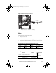
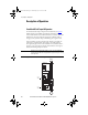
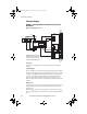
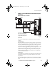

Table Of Contents
- Front Cover/Table of Contents
- General Description
- What Is the DriveGuard Safe Torque Off Option?
- Certifications and Compliance
- CE Certification
- Certified Equipment
- Important Safety Considerations
- Safe State
- Safety Category 3 / PL (d) Performance Definition
- Stop Category Definitions
- Performance Level and Safety Integrity Level (SIL) CL2
- PFD and PFH Definitions
- PFD and PFH Data
- Functional Proof Tests
- Contact Information if Safety Option Failure Occurs
- Installation and Wiring
- Pre-Installation Instructions
- EMC Considerations
- DriveGuard Safe Torque Off Option Installation
- Wiring
- Verify Operation
- Description of Operation
- PowerFlex 40P Safe Torque Off Operation
- PowerFlex 70 Safe Torque Off Operation
- Connection Examples
- Back Cover
Rockwell Automation Publication PFLEX-UM003B-EN-P - July 2012 21
Description of Operation
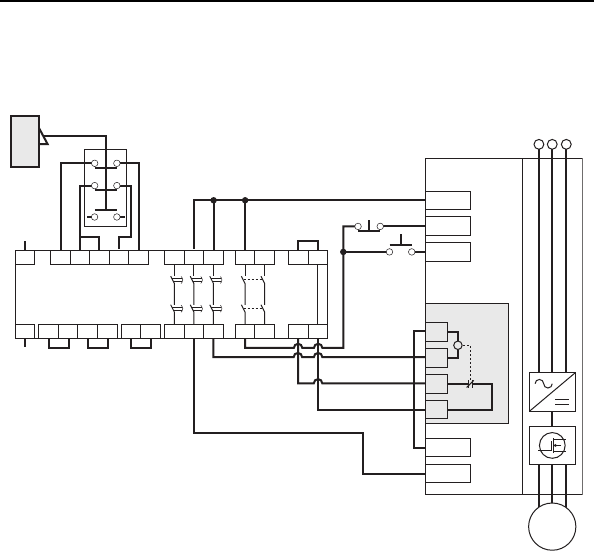
Example 2 - Safe Torque Off Connection with Controlled Stop Action,
Dual Channel
Figure 11 - Stop Category 1 – Controlled
Circuit Status
Circuit shown with guard door closed and system ready for normal drive
operation.
Operating Principle
This is a dual channel system with monitoring of the Safe Torque Off circuit
and drive. Opening the guard door will switch the input circuits (S11-S12 &
S21-S22) to the Minotaur monitoring safety relay unit. The output circuits
(13-14) issue a Stop command to the drive and cause a controlled
deceleration. After the programmed delay, the timed output circuits (47-48 &
57-58) will cause the Safe Torque Off option and the drive Enable circuit to
trip. If the motor is rotating when the trip occurs, it will coast to stop. To
restart the drive, the Minotaur safety relay must first be reset followed by a
valid start command to the drive.
Fault Detection
A single fault detected on the Minotaur safety input circuits will result in the
lock-out of the system at the next operation and will not cause loss of the
safety function.
If the Safe Torque Off option sticks ON, the motor will stop on command
due to the enable input. The system cannot be reset when this fault condition
exists.
+24V DC
Common
+24V DC
GuardMaster
Trojan
Stop
Start
A1 S21 S11 S52 S12
A2 X1 X2
13 23
14 24
S33
Y2
S34
Y1X3
37 47 57
38 48 58X4
S22
Y39 Y40
Minotaur
MSR138DP
Gate
+24V DC
PowerFlex
AC Drive
Stop
Start
AC Line
Input Power
Common
Enable *
M
1
2
3
4
Safe O Option
*Important: The drive Enable digital
input is a solid state circuit. The safety
outputs on safety module must not be
configured for Pulsed/Safety Pulse Test.
PFLEX-UM003.fm Page 21 Wednesday, July 18, 2012 8:26 AM