
User Manual - Series B Instruction Manual
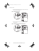
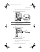
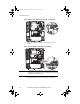
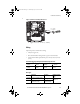
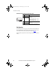
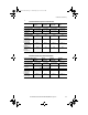
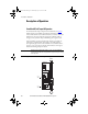
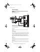
Table Of Contents
- Front Cover/Table of Contents
- General Description
- What Is the DriveGuard Safe Torque Off Option?
- Certifications and Compliance
- CE Certification
- Certified Equipment
- Important Safety Considerations
- Safe State
- Safety Category 3 / PL (d) Performance Definition
- Stop Category Definitions
- Performance Level and Safety Integrity Level (SIL) CL2
- PFD and PFH Definitions
- PFD and PFH Data
- Functional Proof Tests
- Contact Information if Safety Option Failure Occurs
- Installation and Wiring
- Pre-Installation Instructions
- EMC Considerations
- DriveGuard Safe Torque Off Option Installation
- Wiring
- Verify Operation
- Description of Operation
- PowerFlex 40P Safe Torque Off Operation
- PowerFlex 70 Safe Torque Off Operation
- Connection Examples
- Back Cover

Rockwell Automation Publication PFLEX-UM003B-EN-P - July 2012 17
Installation and Wiring
PowerFlex 40P Channel Operation and Verification
PowerFlex 70 Channel Operation and Verification
Safety Function Status Drive In
Safe State
Drive In
Stopped State
Drive In
Stopped State
Drive Able
To Run
Safety Channel Operation
Safe Torque Off Option
Terminals 3 & 4
No Power Applied Power Applied No Power Applied Power Applied
PowerFlex 40P
Enable Input
No Power Applied No Power Applied Power Applied Power Applied
Description For Verification
Safe Torque Off Option
Monitor Contact
Terminals 1 & 2
Closed Open Closed Open
PowerFlex 40P
[Control In Status]
Param. 13, Bit 2
Value = 0Value = 0Value = 1Value = 1
PowerFlex 40P
Comms Status Word
8448, Bit 0
Value = 0Value = 0Value = 0Value = 1
Safe Torque Off
Output
(1)
Relay N.O.
Dig Output States
Closed Open Open Open
(1) Must set A055 [Relay Out Sel], A058 or A061 [Opto Outx Sel] to option 25 “Safe-Off”.
Safety Function Status Drive In
Safe State
Drive In
Stopped State
Drive In
(1)
Stopped State
Drive Able
To Run
Safety Channel Operation
Safe Torque Off Option
Terminals 3 & 4
No Power Applied Power Applied No Power Applied Power Applied
PowerFlex 70
Enable Input
No Power Applied No Power Applied Power Applied Power Applied
Description For Verification
Safe Torque Off Option
Monitor Contact
Terminals 1 & 2
Closed Open Closed Open
PowerFlex 70
Drive Inhibits
Param. 214, Bit 2
Value = 1 Value = 1 Value = 0 Value = 0
(1) A Start/Run command will cause an F111 “Enable Hardware” fault.
PFLEX-UM003.fm Page 17 Wednesday, July 18, 2012 8:26 AM