
User Manual - Series B Instruction Manual
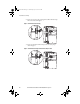
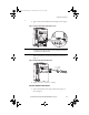
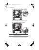
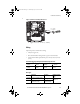
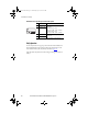
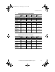
Table Of Contents
- Front Cover/Table of Contents
- General Description
- What Is the DriveGuard Safe Torque Off Option?
- Certifications and Compliance
- CE Certification
- Certified Equipment
- Important Safety Considerations
- Safe State
- Safety Category 3 / PL (d) Performance Definition
- Stop Category Definitions
- Performance Level and Safety Integrity Level (SIL) CL2
- PFD and PFH Definitions
- PFD and PFH Data
- Functional Proof Tests
- Contact Information if Safety Option Failure Occurs
- Installation and Wiring
- Pre-Installation Instructions
- EMC Considerations
- DriveGuard Safe Torque Off Option Installation
- Wiring
- Verify Operation
- Description of Operation
- PowerFlex 40P Safe Torque Off Operation
- PowerFlex 70 Safe Torque Off Operation
- Connection Examples
- Back Cover
16 Rockwell Automation Publication PFLEX-UM003B-EN-P - July 2012
Installation and Wiring
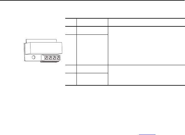
DriveGuard Safe Torque Off Option Terminal Description
Verify Operation
Test the safety function for proper operation after the initial installation of
the DriveGuard Safe Torque Off option. Retest the safety function at the
intervals determined by the safety analysis described on page 10
.
Verify that both safety channels are functioning according to the Table 4 or
Table 5.
No. Signal Description
1 Monitor - N.C. Normally closed contacts for monitoring
relay status.
Maximum Resistive Load:
250V AC / 30V DC / 50 VA / 60 Watts
Maximum Inductive Load:
250V AC / 30V DC / 25 VA / 30 Watts
2 Common - N.C.
3 +24V DC Connections for user supplied power to
energize coil.
33.3 mA typical, 55 mA maximum.
424V Common
1234
PFLEX-UM003.fm Page 16 Wednesday, July 18, 2012 8:26 AM