
User Manual - Series B Instruction Manual
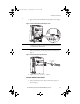
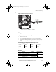
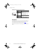
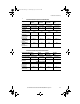
Table Of Contents
- Front Cover/Table of Contents
- General Description
- What Is the DriveGuard Safe Torque Off Option?
- Certifications and Compliance
- CE Certification
- Certified Equipment
- Important Safety Considerations
- Safe State
- Safety Category 3 / PL (d) Performance Definition
- Stop Category Definitions
- Performance Level and Safety Integrity Level (SIL) CL2
- PFD and PFH Definitions
- PFD and PFH Data
- Functional Proof Tests
- Contact Information if Safety Option Failure Occurs
- Installation and Wiring
- Pre-Installation Instructions
- EMC Considerations
- DriveGuard Safe Torque Off Option Installation
- Wiring
- Verify Operation
- Description of Operation
- PowerFlex 40P Safe Torque Off Operation
- PowerFlex 70 Safe Torque Off Operation
- Connection Examples
- Back Cover
Rockwell Automation Publication PFLEX-UM003B-EN-P - July 2012 15
Installation and Wiring
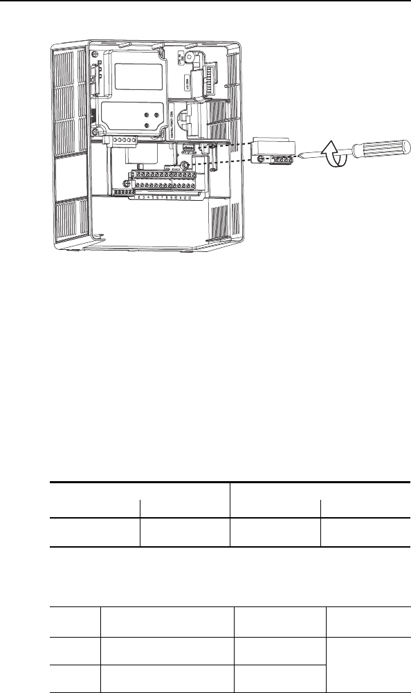
Figure 7 - PowerFlex 70 Safe Torque Off Connector
4. Tighten screw to 0.8…1.1 N•m (7…10 lb•in).
Wiring
Important points to remember about wiring:
•Always use copper wire.
• Wire with an insulation rating of 600V or greater is recommended.
• Control wires should be separated from power wires by at least 0.3 meters
(1 foot).
DriveGuard Safe Torque Off Option Terminal Block Specifications
Wire Types
Wire Size Range
(1)
(1) Maximum / minimum that the terminal block will accept - these are not recommendations.
Torque
Maximum Minimum Maximum Recommended
1.5 mm
2
(16 AWG)
0.14 mm
2
(26 AWG)
0.25 N•m
(2.2 lb•in)
0.22 N•m
(1.9 lb•in)
Wire Type(s) Description Minimum Insulation
Rating
Unshielded Per US NEC or applicable national or
local code
—300V,
60 degrees C
(140 degrees F)
Shielded Multi-conductor shielded cable such
as Belden 8770(or equiv.)
0.750 mm
2
(18AWG),
3 conductor, shielded.
0.8…1.1 N•m
(7…10 lb•in)
PFLEX-UM003.fm Page 15 Wednesday, July 18, 2012 8:26 AM