
User Manual - Series B Instruction Manual
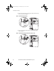
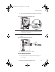
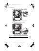
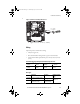
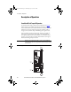
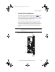
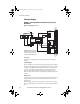
Table Of Contents
- Front Cover/Table of Contents
- General Description
- What Is the DriveGuard Safe Torque Off Option?
- Certifications and Compliance
- CE Certification
- Certified Equipment
- Important Safety Considerations
- Safe State
- Safety Category 3 / PL (d) Performance Definition
- Stop Category Definitions
- Performance Level and Safety Integrity Level (SIL) CL2
- PFD and PFH Definitions
- PFD and PFH Data
- Functional Proof Tests
- Contact Information if Safety Option Failure Occurs
- Installation and Wiring
- Pre-Installation Instructions
- EMC Considerations
- DriveGuard Safe Torque Off Option Installation
- Wiring
- Verify Operation
- Description of Operation
- PowerFlex 40P Safe Torque Off Operation
- PowerFlex 70 Safe Torque Off Operation
- Connection Examples
- Back Cover
14 Rockwell Automation Publication PFLEX-UM003B-EN-P - July 2012
Installation and Wiring
Figure 5 - PowerFlex 70 Safe Torque Off Connection Jumper Location (Typical)
2. Remove the PowerFlex 70 Hardware Enable jumper as shown in
Figure 6.
Figure 6 - PowerFlex 70 Hardware Enable Jumper Location (Typical)
3. Plug the DriveGuard Safe Torque Off option (Series A or greater)
into the PowerFlex 70 four pin connector as shown in Figure 7.
IMPORTANT
The PowerFlex 70 hardware enable jumper must be removed when using the
DriveGuard Safe Torque Off option. Failure to remove the jumper will cause the drive
to fault when a start command is issued.
PFLEX-UM003.fm Page 14 Wednesday, July 18, 2012 8:26 AM