
User Manual - Series B Instruction Manual
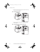
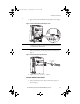
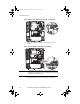
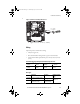
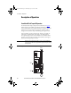
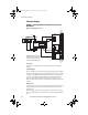
Table Of Contents
- Front Cover/Table of Contents
- General Description
- What Is the DriveGuard Safe Torque Off Option?
- Certifications and Compliance
- CE Certification
- Certified Equipment
- Important Safety Considerations
- Safe State
- Safety Category 3 / PL (d) Performance Definition
- Stop Category Definitions
- Performance Level and Safety Integrity Level (SIL) CL2
- PFD and PFH Definitions
- PFD and PFH Data
- Functional Proof Tests
- Contact Information if Safety Option Failure Occurs
- Installation and Wiring
- Pre-Installation Instructions
- EMC Considerations
- DriveGuard Safe Torque Off Option Installation
- Wiring
- Verify Operation
- Description of Operation
- PowerFlex 40P Safe Torque Off Operation
- PowerFlex 70 Safe Torque Off Operation
- Connection Examples
- Back Cover

Rockwell Automation Publication PFLEX-UM003B-EN-P - July 2012 11
Installation and Wiring
EMC Considerations
The DriveGuard Safe Torque Off option and PF40P and PF70 drives may be
installed in an industrial electromagnetic environment which is consistent
with the “Second Environment” described in IEC 61800-3 and where the
EMC requirements documented in the PF40P and PF70 Installation manuals
have been satisfied. Important installation requirements include:
• All motor output, control (I/O) and signal wiring for the drive and
DriveGuard Safe Torque Off option must be shielded cable
• Grounding (earthing) must conform to the requirements described in the
drive user manuals
DriveGuard Safe Torque Off Option Installation
PowerFlex 40P Drives
1. Remove all power to the drive.
ATTENTION: To avoid an electric shock hazard, verify that the voltage on the bus
capacitors has discharged before performing any work on the drive. Measure the DC bus
voltage at the +DC and -DC terminals or test points (refer to your drive’s User Manual for
locations). The voltage must be zero.
PFLEX-UM003.fm Page 11 Wednesday, July 18, 2012 8:26 AM