
Owner manual

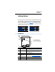
Table Of Contents
- PowerFlex 22-COMM-P Profibus Adapter User Manual
- Summary of Changes
- Table of Contents
- Preface
- Chapter 1
- Chapter 2
- Chapter 3
- Chapter 4
- Chapter 5
- Chapter 6
- Chapter 7
- Chapter 8
- Appendix A
- Appendix B
- Appendix C
- Appendix D
- Glossary
- Index
- Back Cover / Publication 22COMM-UM005E-EN-P June 2012
Chapter 1
Getting Started
The adapter is intended for installation into a PowerFlex 40, PowerFlex 40P or
PowerFlex 400 drive and is used for network communication. The adapter can
also be installed in a DSI External Comms Kit (22-XCOMM-DC-BASE).
When operated in Multi-Drive mode (Chapter
7), the adapter provides the
means for up to five (5) PowerFlex 4-Class drives to operate on the network
and be represented as only one node.
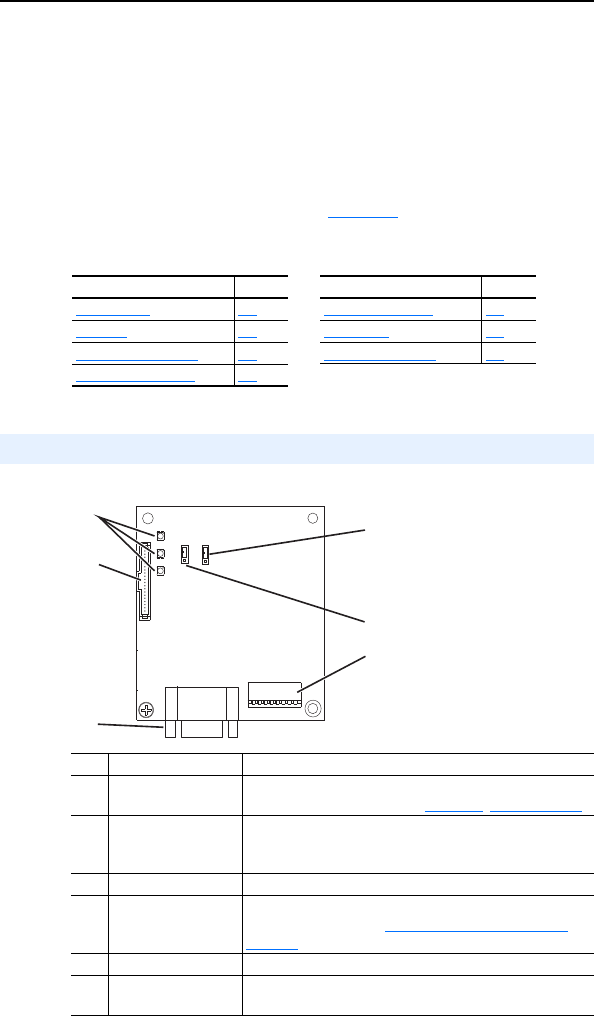
Figure 1.1 Components of the Adapter
Topic Page Topic Page
Components
1-1 Safety Precautions 1-5
Features 1-2 Quick Start 1-6
Compatible Products 1-3 Status of Operation 1-7
Required Equipment 1-3
Components
Item Part Description
➊ Status Indicators Three LEDs that indicate the status of the adapter and
network communications. See Chapter
8, Troubleshooting
➋ DSI Connector A 20-pin, single-row shrouded male header. An Internal
Interface cable is connected to this connector and a
connector on the drive.
➌ Profibus Connector A 9-pin, female D-Sub connector.
➍ Node Address/
Firmware Update
Switches
Switches SW1…SW7 to set the node address and SW8 for
firmware updating. See Commissioning the Adapter
on
page 2-1.
➎ Mode Jumper (J2) Selects Single mode or Multi-Drive mode of operation.
➏ SWAP Jumper (J3) Determines the Intel or Motorola (SWAP) data format for
the corresponding PLC.
➊
➋
➌
➍
➎
❻
Series A adapter shown;
Series B adapter Jumper J2
and J3 locations are different