
Owner manual
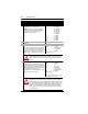
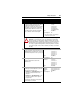
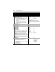

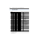
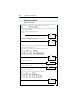
Table Of Contents
- PowerFlex 22-COMM-P Profibus Adapter User Manual
- Summary of Changes
- Table of Contents
- Preface
- Chapter 1
- Chapter 2
- Chapter 3
- Chapter 4
- Chapter 5
- Chapter 6
- Chapter 7
- Chapter 8
- Appendix A
- Appendix B
- Appendix C
- Appendix D
- Glossary
- Index
- Back Cover / Publication 22COMM-UM005E-EN-P June 2012

C-2 PowerFlex 4-Class Drives Logic Command/Status Words
Logic Status Word
Logic Bits
15 14 13 12 11 10 9 8 7 6 5 4 3 2 1 0 Status Description
x Ready 0 = Not Ready
1 = Ready
x Active 0 = Not Active
1 = Active
xCommand
Direction
0 = Reverse
1 = Forward
x Actual
Direction
0 = Reverse
1 = Forward
x Accel 0 = Not Accelerating
1 = Accelerating
x Decel 0 = Not Decelerating
1 = Decelerating
x Alarm 0 = No Alarm
1 = Alarm
x Fault 0 = No Fault
1 = Fault
x At Speed 0 = Not At Reference
1 = At Reference
x Main Freq
(1)
0 = Not Controlled By Comm
1 = Controlled By Comm
x Operation
Command
(1)
0 = Not Controlled By Comm
1 = Controlled By Comm
x Parameters
(1)
0 = Not Locked
1 = Locked
x Digital Input 1
Status
(1)
x Digital Input 2
Status
(1)
x Digital Input 3
Status
(1)
(2)
x Digital Input 4
Status
(1)
(2)
(1)
The functions for these bits are the same for all PowerFlex 4-Class drives—including the PowerFlex 40P when it is used in the
“Velocity” mode. When using the PowerFlex 40P in the “Position” mode, the bit functions are different. For details, see Appendix
C in the PowerFlex 40P User Manual.
(2)
This status is available for only PowerFlex 40 drives with firmware revision 2.xx (or later). For PowerFlex 4 and PowerFlex 4M
drives, these bits are not used.