
Owner manual

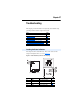
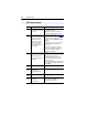
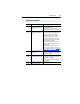
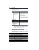
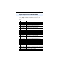
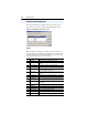
Table Of Contents
- PowerFlex 22-COMM-P Profibus Adapter User Manual
- Summary of Changes
- Table of Contents
- Preface
- Chapter 1
- Chapter 2
- Chapter 3
- Chapter 4
- Chapter 5
- Chapter 6
- Chapter 7
- Chapter 8
- Appendix A
- Appendix B
- Appendix C
- Appendix D
- Glossary
- Index
- Back Cover / Publication 22COMM-UM005E-EN-P June 2012

8-4 Troubleshooting
NOTE: For the Multi Drive mode, disconnecting a DSI cable from a
daisy-chained drive does not lead to an error! There is no
indication in the adapter that a drive is missing, except that
commands to the missing drive have no effect.
The following diagnostic items can be accessed using a PowerFelx
4-Class HIM, DriveExplorer or DriveExecutive (version 3.01 or higher).
NET A Status Indicator
Status Cause Corrective Actions
Off The adapter is not powered
or is not connected
properly to the network or
the Node Address is
incorrect.
• Securely connect the adapter to the drive
using the Internal Interface (ribbon) cable and
to the network using a Profibus cable. (Screw
D-shell to the adapter).
• Check the SW8 of DIP-Switches and set it to
one - Normal operating state.
• Check the DIP-Switches (SW1…SW7) node
address and the Scanner setting.
• Apply power to the drive cable (or adapter if
mounted in a DSI External Comms Kit).
Flashing
Red
Error in Profibus
configuration.
Re-configure the Profibus module.
Solid
Red
Not used. —
Flashing
Green
Not used. —
Solid
Green
The adapter is properly
connected and
communicating on the
network.
No action required.
Adapter Diagnostic Items in Single Mode
No. Name Description
1 Field Flash Cnt The number of Firmware Updates.
2 Adapter Events The number of events in the event queue.
3 Reference Reference from Profibus returned to DSI drive.
4 Logic Cmd Command from Profibus returned to DSI drive.
5 Logic Sts Status of the drive returned to Profibus.
6 Feedback Feedback from drive returned to Profibus.
7 Profibus Rx Errors Current value of the Profibus Receive Error Counter register.
8 Profibus Tx Errors Current value of the Profibus Transmit Error Counter register.
9 Data Rate Current setting of the Profibus baud rate.
10 Node Address Current setting of the adapter Node address switch.