
Owner manual
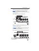
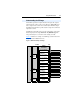
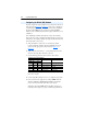
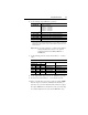
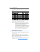
Table Of Contents
- PowerFlex 22-COMM-P Profibus Adapter User Manual
- Summary of Changes
- Table of Contents
- Preface
- Chapter 1
- Chapter 2
- Chapter 3
- Chapter 4
- Chapter 5
- Chapter 6
- Chapter 7
- Chapter 8
- Appendix A
- Appendix B
- Appendix C
- Appendix D
- Glossary
- Index
- Back Cover / Publication 22COMM-UM005E-EN-P June 2012

Using Multi-Drive Mode 7-9
6. Set the following adapter Multi-Drive parameters:
Important: To set adapter parameters, you must use DriveExplorer
software, DriveExecutive software or an optional,
external PowerFlex 4-Class HIM (22-HIM-A3 or
22-HIM-C2S).
7. Set the following parameters in daisy-chained Drives 1…4 to these
values:
8. Set the adapter Mode Jumper J2 to the “5x” (Multi-Drive) position.
9. Reconnect daisy-chained Drives 1…4 to the RS-485 network.
10. Power cycle ALL drives on the node to apply new settings. NOTE:
When the adapter is installed in a DSI External Comms Kit, you
must also power cycle the Comms Kit, which will reset the adapter.
The adapter PORT indicator should now be steady green, indicating
successfull configuration of the daisy-chained Multi-Drive node.
Adapter Parameter Value
11 - [DSI I/O Cfg] 0 = Drive 0 connected
1 = Drives 0…1 connected
2 = Drives 0…2 connected
3 = Drives 0…3 connected
4 = Drives 0…4 connected
17 - [Drv 0 Addr]
(1)
(1)
The settings for these parameters must match the [Comm Node Addr] parameter values for the
respective drives. The [Comm Node Addr] parameter is A104 for PowerFlex 4, PowerFlex 40,
and PowerFlex 40P drives, parameter C303 for PowerFlex 4M drives, and parameter C104 for
PowerFlex 400 drives.
Equal to Drive 0 [Comm Node Address] Parameter
18 - [Drv 1 Addr]
(1)
Equal to Drive 1 [Comm Node Address] Parameter
19 - [Drv 2 Addr]
(1)
Equal to Drive 2 [Comm Node Address] Parameter
20 - [Drv 3 Addr]
(1)
Equal to Drive 3 [Comm Node Address] Parameter
21 - [Drv 4 Addr]
(1)
Equal to Drive 4 [Comm Node Address] Parameter
PowerFlex 4-Class Drive Parameter
Number Name Value
4/40/40P 4M 400
P36 P106 P36 [Start Source] 5 (Comm Port)
P38 P108 P38 [Speed Reference] 5 (Comm Port)
A103 C302 C103 [Comm Data Rate] 4 (19.2K)
A104 C303 C104 [Comm Node Addr] 1…247 (must be unique)
A107 C306 C102 [Comm Format] 0 (RTU 8-N-1)