
Owner manual
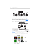
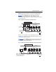
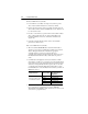
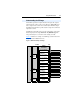
Table Of Contents
- PowerFlex 22-COMM-P Profibus Adapter User Manual
- Summary of Changes
- Table of Contents
- Preface
- Chapter 1
- Chapter 2
- Chapter 3
- Chapter 4
- Chapter 5
- Chapter 6
- Chapter 7
- Chapter 8
- Appendix A
- Appendix B
- Appendix C
- Appendix D
- Glossary
- Index
- Back Cover / Publication 22COMM-UM005E-EN-P June 2012
7-8 Using Multi-Drive Mode
Properly configure the adapter (Single mode operation) and only the 1st
drive (as shown in Figure 7.4
or Figure 7.5) on the node so that they are
communicating with each other. Communication has been established
when the adapter PORT indicator is solid green. When the PORT
indicator is red, communication between the adapter and the drive is not
established.
After establishing communication with the 1st drive, the remaining
drives on the node can be configured. Carefully follow these step-by-step
instructions to successfully configure the adapter and RS-485 network of
daisy-chained drives on the node.
1. Verify that all drives on the node are correctly daisy-chained
together, and that the 120 ohm, 1/4 watt terminating resistors are
connected at the appropriate locations shown in Figure 7.7
or
Figure 7.8
.
2. Temporarily disconnect Drives 1…4 from the RS-485 daisy-chain
network, so that only Drive 0 remains connected.
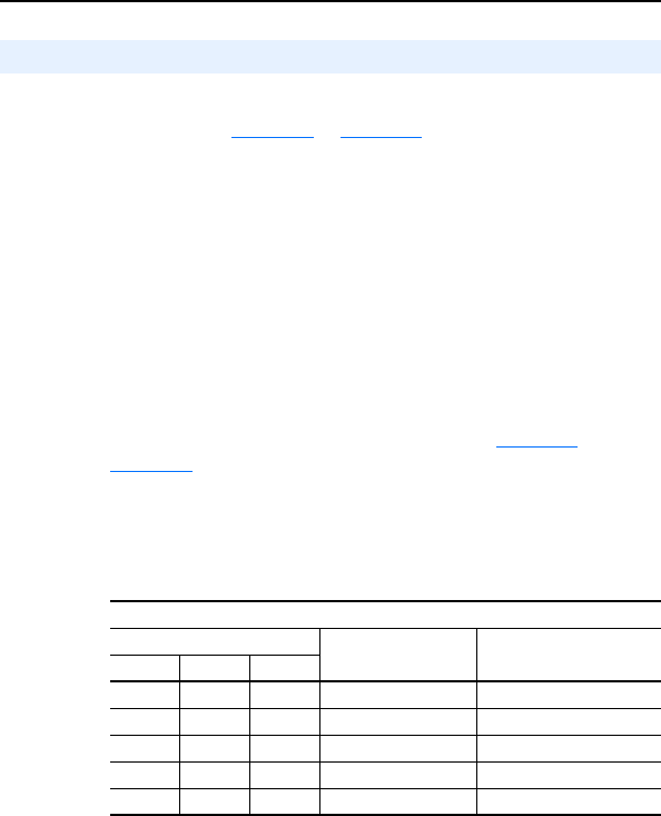
3. Set the following parameters in the 1st drive to these values:
Note that the RS-485 network is fixed at 19.2K baud. 8 data bits, no
parity, and 1 stop bit.
4. Set the adapter Mode Jumper J2 to the “1x” (Single mode) position.
5. Power cycle Drive 0 to apply the new settings. NOTE: When the
adapter is installed in a DSI External Comms Kit, you must also
power cycle the Comms Kit, which will reset the adapter.
At this time, the adapter PORT indicator should be steady green,
indicating that the adapter is properly commuincating with Drive 0.
Configuring the RS-485 (DSI) Network
PowerFlex 4-Class Drive Parameter
Number Name Value
4/40/40P 4M 400
P36 P106 P36 [Start Source] 5 (Comm Port)
P38 P108 P38 [Speed Reference] 5 (Comm Port)
A103 C302 C103 [Comm Data Rate] 4 (19.2K)
A104 C303 C104 [Comm Node Addr] 1…247 (must be unique)
A107 C306 C102 [Comm Format] 0 (RTU 8-N-1)