
Owner manual
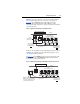
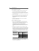
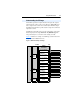
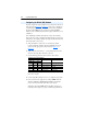
Table Of Contents
- PowerFlex 22-COMM-P Profibus Adapter User Manual
- Summary of Changes
- Table of Contents
- Preface
- Chapter 1
- Chapter 2
- Chapter 3
- Chapter 4
- Chapter 5
- Chapter 6
- Chapter 7
- Chapter 8
- Appendix A
- Appendix B
- Appendix C
- Appendix D
- Glossary
- Index
- Back Cover / Publication 22COMM-UM005E-EN-P June 2012
7-6 Using Multi-Drive Mode
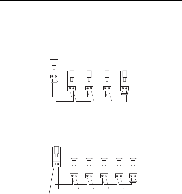
Figure 7.7 and Figure 7.8 show wiring diagrams for using
AK-U0-RJ45-TB2P terminal block connectors and terminating resistors.
Figure 7.7 Connector Wiring Diagram - With Adapter in Drive
Figure 7.8 Connector Wiring Diagram - With Adapter in DSI External Comms Kit
NOTE: When connecting the drives in a Multi-Drive configuration, the
order in which the drives are connected does not matter. That is, Drive 0
can be any of the drives, and Drive 0 does not have to be the drive in
which the adapter is installed (or the drive to which the DSI External
Comms Kit is plugged into).
To Drive 0
(PowerFlex 40/40P/400 drive with
installed 22-COMM-P adapter)
120 Ohm,
¼ Watt
Terminating
Resistor
To
Drive 1
To
Drive 2
To
Drive 3
To
Drive 4
120 Ohm,
¼ Watt
Terminating
Resistor
To DSI External Comms Kit
(with installed 22-COMM-P adapter)
NOTE: A terminating resistor is not
required for this end of the wiring.
The resistor is built into the circuitry
of the DSI External Comms Kit.
To
Drive 1
To
Drive 2
To
Drive 3
To
Drive 4
120 Ohm,
¼ Watt
Te r mi nat in g
Resistor
To
Drive 0