
Owner manual
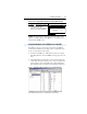
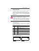
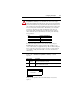
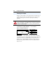
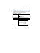

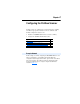
Table Of Contents
- PowerFlex 22-COMM-P Profibus Adapter User Manual
- Summary of Changes
- Table of Contents
- Preface
- Chapter 1
- Chapter 2
- Chapter 3
- Chapter 4
- Chapter 5
- Chapter 6
- Chapter 7
- Chapter 8
- Appendix A
- Appendix B
- Appendix C
- Appendix D
- Glossary
- Index
- Back Cover / Publication 22COMM-UM005E-EN-P June 2012
3-4 Configuring the Adapter
See page 2-2 for details to set the node address.
The I/O configuration determines the number of drives that will be
represented on the network as one node by the adapter. If the Mode
Jumper J2 is set to the “1x” (Single mode) default position, only one
drive is represented by the adapter and Parameter 11 - [DSI I/O Cfg]
has no effect. If the Mode Jumper J2 is set to the “5x” (Multi-Drive)
position, up to five drives can be represented as one node by the adapter.
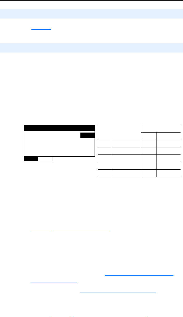
1. Set the value in Parameter 11 - [DSI I/O Cfg].
Figure 3.2 Example DSI I/O Cfg HIM Screen
When the adapter is internally mounted in a PowerFlex 40, PowerFlex
40P or PowerFlex 400 drive, this drive is always Drive 0. Drives 1
through 4 are PowerFlex 4-Class drives that are daisy-chained to the
RJ45 (RS-485) port on Drive 0. When the adapter is remotely
mounted in a DSI External Comms Kit, Drives 0 through 4 are
daisy-chained to the RJ45 (RS-485) port on the Comms Kit. Refer to
Chapter7
, Using Multi-Drive Mode for more information.
2. Configure the parameters in the drive to accept the Logic Command
and Reference from the adapter. In a PowerFlex 40 drive, for
example, set parameter P036 - [Start Source] and parameter P038 -
[Speed Reference] both to “5” (Comm Port). When using the adapter
in Multi-Drive mode, each daisy-chained drive requires that
additional parameters be set. See Configuring the RS-485 (DSI)
Network on page 7-8 for these parameters and their settings.
3. Reset the adapter. See Resetting the Adapter
on page 3-8.
The adapter is ready to receive I/O from the master (that is, scanner).
You must now configure the scanner to recognize and transmit I/O to the
adapter. See Chapter4
, Configuring the Profibus Scanner.
Setting the Node Address
Setting the I/O Configuration
Value Description
Mode Jumper Setting
Single Multi-Drive
0 Drive 0 (Default) ✓✓
1Drives 0…1 ✓
2Drives 0…2 ✓
3Drives 0…3 ✓
4Drives 0…4 ✓
DSI I/O Cfg
Parameter: #
011
Drive 0 0
VALUE LIMITS SEL