
Owner manual
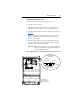
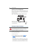
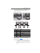

Table Of Contents
- PowerFlex 22-COMM-P Profibus Adapter User Manual
- Summary of Changes
- Table of Contents
- Preface
- Chapter 1
- Chapter 2
- Chapter 3
- Chapter 4
- Chapter 5
- Chapter 6
- Chapter 7
- Chapter 8
- Appendix A
- Appendix B
- Appendix C
- Appendix D
- Glossary
- Index
- Back Cover / Publication 22COMM-UM005E-EN-P June 2012
Installing the Adapter 2-5
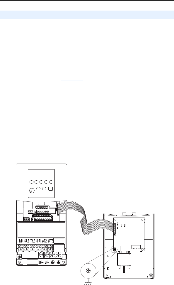
PowerFlex 40/40P Frames B and C, and PowerFlex 400 Frame C
1. Remove power from the drive, and remove the drive cover.
2. Use static control precautions.
3. Mount the adapter on the required special drive cover (ordered
separately; see Figure 2.3
for part numbers).
– Frame B: Do not use the adapter screw; snap the adapter in place.
– Frame C: Use the adapter screw to secure the adapter to the cover.
Important: To properly ground the adapter in Frame B drives, install
the special drive cover onto the drive using both cover
fasteners. To ground the adapter in Frame C drives,
tighten the adapter’s lower left screw (Figure 2.3
). In
either case, tighten the screw(s) to the recommended
torque (0.9 N•m/8.0 lb•in) to properly ground the adapter.
Figure 2.3 Mounting and Grounding the Adapter – PowerFlex 40/40P Frames B
and C, and PowerFlex 400 Frame C
Connecting the Adapter to the Drive
Ground for Frame C Drives
NOTE: For Frame B drives, the lower left adapter screw does
not ground the adapter. To ground the adapter, install the
special drive cover onto the drive using both cover fasteners.
Adapter Mounted on Back of
Required Special Drive Cover
(Frame C cover shown)
PowerFlex 40/40P Frame B – Part No. 22B-CCB
PowerFlex 40/40P Frame C – Part No. 22B-CCC
PowerFlex 400 Frame C – Part No. 22C-CCC
PowerFlex 40 Drive (Frame C
shown with cover removed)
0.9 N•m
(8.0 lb•in)