
Owner manual
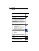
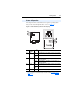

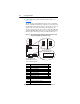
Table Of Contents
- PowerFlex 22-COMM-P Profibus Adapter User Manual
- Summary of Changes
- Table of Contents
- Preface
- Chapter 1
- Chapter 2
- Chapter 3
- Chapter 4
- Chapter 5
- Chapter 6
- Chapter 7
- Chapter 8
- Appendix A
- Appendix B
- Appendix C
- Appendix D
- Glossary
- Index
- Back Cover / Publication 22COMM-UM005E-EN-P June 2012

1-6 Getting Started
This section is designed to help experienced users start using the adapter.
If you are unsure how to complete a step, see the referenced chapter.
Quick Start
Step Action See…
1 Review the safety precautions for the adapter. Throughout
manual
2 Verify that the PowerFlex drive is properly installed. Drive User
Manual
3 Commission the adapter.
Set a unique node address using the DIP-switch for Bit 1 to 7
on the adapter.
Chapter
2,
Installing the
Adapter
4 Install the adapter.
Verify that the PowerFlex drive and Profibus network are not
powered. Then, connect the adapter to the network using a
Profibus cable and to the drive using the internal Interface
cable. Use the captive screws to secure and ground the
adapter to the drive.
5 Apply power to the adapter.
The adapter receives power from the drive. Apply power to the
drive. The status indicators should be green. If they flash red,
there is a problem.
6 Set up the drive parameters.
Before starting, configuring, and working with the Profibus
adapter, set the following drive parameters:
• P036 [Start Source] to “5” (RS485 DSI port) if Start is
controlled from the network.
• P038 [Speed Reference] to “5” (RS485 DSI port) if the
Speed Reference is controlled from the network.
Page 3-4
For Multi Drive mode, the following additional drive
parameters must be set: A103, A104, A107.
Page 7-8
7 Configure the adapter for your application.
Set the following parameters for the adapter as required by
your application:
• Node address
• I/O configuration
• Fault actions
Chapter
3,
Configuring the
Adapter
8 Apply power to Profibus master and other network devices.
Verify that the master and network are installed and functioning
in accordance with Profibus standards, and then apply power
to them.
9 Configure scanner to communicate with the adapter.
Use a network tool for Profibus to configure the master on the
network.
Chapter
4,
Configuring the
Profibus Scanner
10 Create a ladder logic program.
Use a programming tool such as RSLogix to create a ladder
logic program that enables you to do the following:
• Control the adapter and connected drive.
• Monitor or configure the drive using Parameter Messaging.
Appendix D,
SLC Ladder Logic
Examples