
Owner manual
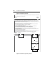
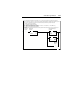


Table Of Contents
- PowerFlex 22-COMM-P Profibus Adapter User Manual
- Summary of Changes
- Table of Contents
- Preface
- Chapter 1
- Chapter 2
- Chapter 3
- Chapter 4
- Chapter 5
- Chapter 6
- Chapter 7
- Chapter 8
- Appendix A
- Appendix B
- Appendix C
- Appendix D
- Glossary
- Index
- Back Cover / Publication 22COMM-UM005E-EN-P June 2012
SLC Ladder Logic Examples D-13
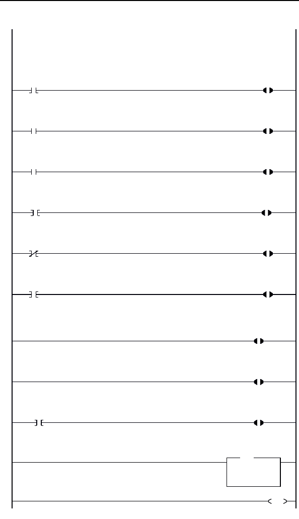
Figure D.7 Drive 0-2 Control/Reference Routine
Controlling the Logic Command word in the drive. B3:22/* bits are controlled elsewhere in the user program.
0
B3:22
0
Station 2
Stop
Command
N20:4
0
Station 2
Logic Command
STOP
1
B3:22
1
Station 2
Start
Command
N20:4
1
Station 2
Logic Command
START
2
B3:22
2
Station 2
Jog
Command
N20:4
2
Station 2
Logic Command
JOG
3
B3:22
3
Station 2
Clear Faults
Command
N20:4
3
Station 2
Logic Command
CLEAR FAULTS
4
B3:22
4
Station 2
Reverse
Command
N20:4
4
Station 2
Logic Command
FORWARD
5
B3:22
4
Station 2
Reverse
Command
N20:4
5
Station 2
Logic Command
REVERSE
To control the speed reference over the Profibus, the three Reference Select bits (bits 14-12) need to have the values 011.
6
N20:4
12
Station 2
Logic Command
REFERENCE SELECT 0
7
N20:4
13
Station 2
Logic Command
REFERENCE SELECT 1
8
B3:22
5
"Never Closed"
N20:4
14
Station 2
Logic Command
REFERENCE SELECT 2
Station 2 Speed Reference
The PowerFlex 40 parameter 38 - [Speed Reference]
needs to be set to 5 ("RS485 [DSI] ¨Port").
N19.5 is controlled elsewhere in the user program.
9
MOV
Move
Source N19:5
314<
Dest
N20:5
0<
MOV
Station 2
Speed Reference
Write
10
END