PowerFlex® 22-COMM-P Profibus Adapter Series A FRN 1.xxx-3.xxx Series B FRN 3.
Important User Information Solid state equipment has operational characteristics differing from those of electromechanical equipment. Safety Guidelines for the Application, Installation and Maintenance of Solid State Controls (Publication SGI-1.1 available from your local Rockwell Automation sales office or online at http:// www.rockwellautomation.com/literature) describes some important differences between solid state equipment and hard-wired electromechanical devices.
Summary of Changes The information below summarizes the changes made to this manual since its last release (December 2011): Description of Changes Page In Chapter 3: • Added new setting “5” (Fault&ClrCmd) to Parameters 9 - [Comm Fault 3-5 Action] and 10 - [Idle Fault Action]. 3-6 • Added new section “Setting DSI Loss Action.” In Chapter 7, added more information throughout about Multi-Drive mode. 7-1 thru 7-5 In Appendix B: • Added new setting “5” (Fault&ClrCmd) to Parameter 9 - [Comm Fault B-2 Action].
soc-ii Summary of Changes
Table of Contents Preface About This Manual Related Documentation . . . . . . . . . . . . . . . . . . . . . . . . . . . . . P-1 Conventions Used in this Manual . . . . . . . . . . . . . . . . . . . . . P-2 Rockwell Automation Support. . . . . . . . . . . . . . . . . . . . . . . . P-2 Chapter 1 Getting Started Components . . . . . . . . . . . . . . . . . . . . . . . . . . . . . . . . . . . . . . Features . . . . . . . . . . . . . . . . . . . . . . . . . . . . . . . . . . . . . . . . .
ii Table of Contents Chapter 6 Using the Parameter Messaging About the Parameter Messaging . . . . . . . . . . . . . . . . . . . . . . 6-1 Running the Parameter Messaging . . . . . . . . . . . . . . . . . . . . 6-2 Parameter Protocol . . . . . . . . . . . . . . . . . . . . . . . . . . . . . . . . . 6-3 Chapter 7 Using Multi-Drive Mode Single Mode versus Multi-Drive Mode . . . . . . . . . . . . . . . . . 7-1 Additional Information . . . . . . . . . . . . . . . . . . . . . . . . . . . . .
Preface About This Manual Topic Page Related Documentation P-1 Conventions Used in this Manual P-2 Rockwell Automation Support P-2 Related Documentation For… See… Publication DriveExplorer™ http://www.ab.com/drives/driveexplorer/, and DriveExplorer online help — DriveTools™ SP (includes http://www.ab.
P-2 About This Manual Conventions Used in this Manual The following conventions are used throughout this manual: • Parameter names are shown in the format Parameter xx - [*]. The xx represents the parameter number. The * represents the parameter name—for example Parameter 04 - [P-DP Addr Actual]. • Menu commands are shown in bold type face and follow the format Menu > Command. For example, if you read “Select File > Open,” you should click the File menu and then click the Open command.
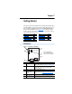
Chapter 1 Getting Started The adapter is intended for installation into a PowerFlex 40, PowerFlex 40P or PowerFlex 400 drive and is used for network communication. The adapter can also be installed in a DSI External Comms Kit (22-XCOMM-DC-BASE). When operated in Multi-Drive mode (Chapter 7), the adapter provides the means for up to five (5) PowerFlex 4-Class drives to operate on the network and be represented as only one node.
1-2 Getting Started Features The adapter features include: • Typical mounting in a PowerFlex 40, PowerFlex 40P or PowerFlex 400 drive. It can also be installed in a DSI External Comms Kit (22-XCOMM-DC-BASE). • The low seven bits of 8-bit DIP switch let you set a node address, and the MSB bit provides write access for the Flash update of module firmware. • Single mode or Multi-Drive mode of operation selected with the adapter Mode Jumper J2.
Getting Started 1-3 Compatible Products The adapter is compatible with Allen-Bradley PowerFlex 4-Class drives and other products that support an internal DSI adapter.
1-4 Getting Started User-Supplied Equipment To install and configure the adapter, you must supply: ❑ A small flathead screwdriver ❑ Profibus cable – One 9-pin, male D-Sub PROFIBUS connector. [Note: PROFIBUS connectors are available from a variety of sources and in various sizes. As such, there may be mechanical limitations that prohibit the use of some connectors.
Getting Started 1-5 Safety Precautions Please read the following safety precautions carefully. ! ! ! ! ! ! ATTENTION: Risk of injury or death exists. The PowerFlex drive may contain high voltages that can cause injury or death. Remove all power from the PowerFlex drive, and then verify power has been removed before installing or removing an adapter. ATTENTION: Risk of injury or equipment damage exists.
1-6 Getting Started Quick Start This section is designed to help experienced users start using the adapter. If you are unsure how to complete a step, see the referenced chapter. Step Action 1 Review the safety precautions for the adapter. 2 Verify that the PowerFlex drive is properly installed. 3 Commission the adapter. Set a unique node address using the DIP-switch for Bit 1 to 7 on the adapter. Install the adapter. Verify that the PowerFlex drive and Profibus network are not powered.
Getting Started 1-7 Status of Operation The adapter uses three status indicators to report its operating status. They can be viewed through the drive cover. See Figure 1.2. Figure 1.2 Status Indicators (location on drive may vary) ➊ ➋ ➌ ➊ ➋ ➌ ➍ Item Status Indicator Status(1) Description ➊ Green Normal Operation. The adapter is properly connected and is communicating with the drive. Flashing Green Not used Green Normal Operation. The adapter is operational and is transferring I/O data.
1-8 Notes: Getting Started
Chapter 2 Installing the Adapter This chapter provides instructions for installing the adapter in a PowerFlex 40, PowerFlex 40P or PowerFlex 400 drive. This adapter can also be installed in a DSI External Comms Kit. In this case, refer to the 22-XCOMM-DC-BASE Installation Instructions (publication 22COMM-IN001) supplied with the kit.
2-2 Installing the Adapter 1. Set the adapter Node Address / Firmware Update switches (see Figure 2.1). The Profibus Node Address/Firmware Update State is configurable using an 8-bit DIP switch. The low seven bits set a node address and the valid address allows binary coding of 1 through 125. A new node address setting is recognized only when power is applied to the adapter by power cycling the drive or after an adapter Reset Module command.
Installing the Adapter Figure 2.2 Node Address Switch Settings (UP = OPEN = 1 = Off) Node Addr.
2-4 Installing the Adapter 2. Verify the Network Baud rate, which is set by the network master and depends on cable length (see Glossary). The 22-COMM-P adapter uses the Auto-Baud function, which enables the adapter to recognize the present baud rate and automatically sets itself to the transmission rate used by the master. The adapter supports the following data rates: 9.6 Kbps, 19.2 Kbps, 45.45 Kbps, 93.75 Kbps, 187.5 Kbps, 500 Kbps, 1.5 Mbps, 3 Mbps, 6 Mbps, and 12 Mbps.
Installing the Adapter 2-5 Connecting the Adapter to the Drive PowerFlex 40/40P Frames B and C, and PowerFlex 400 Frame C 1. Remove power from the drive, and remove the drive cover. 2. Use static control precautions. 3. Mount the adapter on the required special drive cover (ordered separately; see Figure 2.3 for part numbers). – Frame B: Do not use the adapter screw; snap the adapter in place. – Frame C: Use the adapter screw to secure the adapter to the cover.
2-6 Installing the Adapter 4. Connect the Internal Interface cable to the DSI port on the drive and then to the mating DSI connector on the adapter. Figure 2.4 Connecting DSI Ports with Internal Interface Cable ➊ 22-COMM-P Adapter ➋ Back of Required Special Drive Cover PowerFlex 40 Drive (Frame C shown with cover removed) ➍ ➌ Item Description ➊ ➋ ➌ ➍ DSI Connector 15.24 cm (6 in.
Installing the Adapter 2-7 PowerFlex 400 Frames D, E, and F 1. Remove power from the drive, and open the drive cover. 2. Use static control precautions. 3. With the adapter board right side up, remove its mounting screw from the lower left hole. Save the screw for mounting in Step 6. 4. Connect the Internal Interface cable to the DSI port on the drive (see Figure 2.5). 5.
2-8 Installing the Adapter DSI External Comms Kit 22-XCOMM-DC-BASE When connecting the adapter to a DSI External Comms Kit, use either an RS-485-rated cable with two connectors (from AK-U0-RJ45-TB2P kit) or an 8-conductor cable such as a standard ethernet patch cord or a 22-RJ45CBL-C20 cable. Figure 2.
Installing the Adapter 2-9 Subcon Plus M1 (Part # 2761826) are recommended for use with PowerFlex 40, PowerFlex 40P, and PowerFlex 400 drives.] Figure 2.7 Connecting to the Cable ERNI Connector Phoenix Subcon Plus M1 Connector Figure 2.8 Network Wiring Diagram B A B A B A B A B A B A Figure 2.
2-10 Installing the Adapter 6. Depending on the switching frequency of the drive, it is optional to use the ferrite cable clamp around the communication cables next to the D-Sub connector, to reduce high frequency emission. See Figure 2.10. Figure 2.10 Optional Clamp-On Ferrite Cable Clamp Install ferrite core within 10 cm (4 in.) of Profibus connector. To meet the requirements of EN55011 Class A or B, the conditions listed below must be satisfied.
Installing the Adapter 2-11 Termination The first and last node on the Profibus network needs to be terminated by using a Profibus connector with terminating resistors (see Figure 2.11). Some connector manufacturers offer standard terminating connectors, such as the yellow ERNI Profibus termination vertical connector (Part # 103659). Standard Profibus node connectors, such as the Phoenix Subcon Plus M1 (Part #2761826), can be configured as a terminating connector by adding resistors Figure 2.
2-12 Notes: Installing the Adapter
Chapter 3 Configuring the Adapter This chapter provides instructions and information for setting the parameters in the adapter.
3-2 Configuring the Adapter Using the Optional, External PowerFlex 4-Class HIM Adapter parameters cannot be accessed using the integral keypad on a PowerFlex 4-Class drive. You must use Drive Explorer or DriveExecutive software, or an optional, external PowerFlex 4-Class HIM (22-HIM-A3 or 22-HIM-C2S). Basic steps to access parameters in the adapter are shown in Table 3.A. For additional HIM information, refer to the PowerFlex 4-Class HIM Quick Reference (publication 22HIM-QR001).
Configuring the Adapter 3-3 Table 3.A Accessing Adapter Parameters Using the HIM (Continued) Step Example Screens 5. Press (Enter) key to access the Mode parameters. Edit the adapter Parameter: parameters using the same techniques that you use to edit drive parameters. Single Drv VALUE RO # 001 0 LIMITS SEL NOTE: All configuration procedures throughout this chapter use the optional, external PowerFlex 4-Class HIM to access parameters in the adapter and show HIM screens.
3-4 Configuring the Adapter Setting the Node Address See page 2-2 for details to set the node address. Setting the I/O Configuration The I/O configuration determines the number of drives that will be represented on the network as one node by the adapter. If the Mode Jumper J2 is set to the “1x” (Single mode) default position, only one drive is represented by the adapter and Parameter 11 - [DSI I/O Cfg] has no effect.
Configuring the Adapter 3-5 Setting a Fault Action By default, when Profibus communication is disrupted (for example, a cable is disconnected) or the master is idle, the drive responds by faulting if it is using I/O from the network. You can configure a different response to communication disruption using Parameter 9 - [Comm Flt Action] and a different response to an idle scanner using Parameter 10 [Idle Flt Action]. ! ATTENTION: Risk of injury or equipment damage exists.
3-6 Configuring the Adapter Changes to these parameters take effect immediately. A reset is not required. If Multi-Drive mode is used, the same fault action is used by the adapter for all of the drives it controls (Drive 0, Drive 0-1 to Drive 0-4). Setting the Fault Configuration Parameters If you set Parameter 9 - [Comm Flt Action] or 10 - [Idle Flt Action] to the “Send Flt Cfg,” the values in the following parameters are sent to the drive after a communications fault occurs and/or the scanner is idle.
Configuring the Adapter ! 3-7 ATTENTION: Risk of injury or equipment damage exists. Parameter 25- [DSI Loss Action] lets you determine the action of the adapter when DSI communication with the drive has been lost. By default, this parameter maintains the Logic Status and Feedback word values sent to the controller at the time DSI communication between the adapter and drive was lost (that is, hold last state).
3-8 Configuring the Adapter Resetting the Adapter Changes to switch settings or some adapter parameters require that you reset the adapter before the new settings take effect. You can reset the adapter by cycling power to the drive or by using the following parameter. ! ATTENTION: Risk of injury or equipment damage exists. If the adapter is transmitting control I/O to the drive, the drive may fault when you reset the adapter. Determine how your drive will respond before resetting a connected adapter.
Configuring the Adapter 3-9 Viewing the Adapter Configuration The following parameters provide information about how the adapter is configured. You can view these parameters at any time. Adapter Parameter Description 01 - [Mode] Displays the adapter operating mode selected with the Mode Jumper J2. Values 0 = Single Drv operation 1 = Multiple Drv operation 04 - [P-DP Addr Actual] Profibus Node Address actually used by the adapter. 05 - [P-DP Rate Actual] Profibus actual operating data rate.
3-10 Notes: Configuring the Adapter
Chapter 4 Configuring the Profibus Scanner Profibus scanners are available from several manufacturers, including SST. This chapter provides instructions on how to utilize the SST Profibus configuration software tool to: • • Install the 22-COMM-P GSD file in the software tool library Configure the SST-PFB-SLC Profibus Scanner.
4-2 Configuring the Profibus Scanner Figure 4.1 Example Profibus Network COMM LED SYS LED Config Port Front Label Profibus Port Station 0 PowerFlex 40 Station 1 PowerFlex 40 Station 2 SST Profibus Configuration Software Tool SST Profibus scanners come with a software tool for configuring the scanner (see Figure 4.2). Figure 4.
Configuring the Profibus Scanner 4-3 Installing 22-COMM-P GSD File in Software Tool Library GSD files are used by software tools to configure the network, i.e. to map and define the I/O in a Profibus scanner. A GSD file is required for each type of adapter on the network. For example: The 22-COMM-P GSD file is “A_B_07FF.gsd” and a copy of the file is provided on a floppy disk with each 22-COMM-P. The file can also be downloaded from the Internet by going to: www.ab.
4-4 Configuring the Profibus Scanner Figure 4.4 Add Profibus Devices Applet Window 4. Find the directory location of the data file(s) you wish to add (typically, the source location is a floppy disk in drive A:). “A_B_07FF.gsd” is the GSD file for the 22-COMM-P as shown in Figure 4.5. Figure 4.5 Adding the GSD File for the Adapter 5. Select “A_B_07FF.gsd” for the 22-COMM-P and click Open.
Configuring the Profibus Scanner 4-5 6. Click on the (+) sign of the Slaves folder as shown in Figure 4.6. Figure 4.6 Masters/Slaves Library Window The software tool will automatically create an Allen-Bradley sub-folder (in the Slaves folder) if it does not already exist. The 22-COMM-P is now shown in the library and the software tool is now ready to configure a 22-COMM-P on a Profibus network.
4-6 Configuring the Profibus Scanner 3. Double-click the SST-PFB-SLC MASTER in the Masters folder in the Library window to add the scanner to the network. 4. A user-defined Name and Description can be given to the scanner. In our example, the scanner will be Station 0 on the network, as shown in Figure 4.7. Figure 4.7 SST-PFB-SLC Master (General) Dialog Box 5. Click on the Parameters tab to view the Scan Cycle Times. In our example, use the default settings as shown in Figure 4.8. Figure 4.
Configuring the Profibus Scanner 4-7 Figure 4.9 COM Port Default Settings 8. The scanner will appear in the network window as shown in Figure 4.10. Double-click on the scanner in the network window. Figure 4.10 Scanner Network Window 9. Double-click on the 22-COMM-P listed in the Allen-Bradley 22-COMM-P library folder. A user-defined Name and Description can be given to this 22-COMM-P. In our example, this device will be Station 1 on the network.
4-8 Configuring the Profibus Scanner 10. Click on the Modules tab. Click Add to view the choice of modules. Figure 4.12 Available Modules: Ctrl/Stat & Ref/Fdbk Window In our example, Station 1 will be controlled using Logic Command/ Status and Reference/Feedback. The Parameter Access will also be used.
Configuring the Profibus Scanner 4-9 12. Click Add to continue adding modules. Select “Parameter Access” and click OK. Figure 4.14 Add Modules: Parameter Access Selection Window 13. The “Parameter Access” module has now been added as shown in Figure 4.15. Figure 4.15 Modules: Parameter Access Viewing Window 14. Click on the SLC Address tab as shown in Figure 4.16. Settings can be chosen to map Station modules to SLC addresses. In our example M1/M0 files are used for Input / Output.
4-10 Configuring the Profibus Scanner Figure 4.16 SLC Address: M1/M0 (Ctrl/Stat & Ref/Fdbk) 15. Parameter Access starts at word 2 in the M1/M0 files. Note that Parameter Access utilizes 4 words. Click OK when finished. Figure 4.17 SLC Address: M1/M0 (Parameter Access) 16. Station 1 is now displayed in the network window. Figure 4.
Configuring the Profibus Scanner 4-11 17. The same steps for configuring Station 1 will be used for configuring Station 2. See previous steps (starting at step 9, Page 4-7) for Configuring the SST-PFB-SLC Profibus Scanner-Station 2 (see Figure 4.19). Figure 4.19 Station 2 Network Window Station 2 is configured as follows: Module M1/M0 Offset Ctrl/Stat & Ref Fdbk Drive 0 6 Parameter Access 8 Note that Station 2 occupies 6 words. 18.
4-12 Configuring the Profibus Scanner 20. Click File and Save As from the tool bar, as a unique File Name. The configuration of the scanner is now complete. Note that cycling power to the scanner is recommended (see Figure 4.21). Figure 4.
Chapter 5 Using I/O Messaging This chapter provides information that explains how to use I/O Messaging to control a PowerFlex 40 drive. ! Topic Page About I/O Messaging 5-1 Understanding the I/O Image 5-2 Using Logic Command/Status 5-3 Using Reference/Feedback 5-3 ATTENTION: Risk of injury or equipment damage exists. The examples in this publication are intended solely for purposes of example. There are many variables and requirements with any application.
5-2 Using I/O Messaging Understanding the I/O Image The Profibus specification requires that the terms input and output be defined from the scanner’s point of view. Therefore, Output I/O is data that is output from the scanner and consumed by the Profibus adapter. Input I/O is status data that is produced by the adapter and consumed as input by the scanner. The I/O image table will vary based on the: • Configuration of the Mode Jumper (J2) on the adapter and Parameter 11 - [DSI I/O Cfg].
Using I/O Messaging 5-3 Using Logic Command/Status The Logic Command is a 16-bit word of control produced by the controller and consumed by the adapter. The Logic Status is a 16-bit word of status produced by the adapter and consumed by the controller. When enabled, the Logic Command/Status word is always word 0 in the I/O image. This manual contains the bit definitions for compatible products available at the time of publication in Chapter C, PowerFlex 4-Class Drives Logic Command/Status Words.
5-4 Notes: Using I/O Messaging
Chapter 6 Using the Parameter Messaging This chapter provides information that explains how to use Parameter Messaging to monitor and configure the adapter and connected PowerFlex 4-Class drive, as well as other peripherals. ! ! Topic Page About the Parameter Messaging 6-1 Running the Parameter Messaging 6-2 Parameter Protocol 6-3 ATTENTION: Risk of injury or equipment damage exists. The examples in this publication are intended solely for purposes of example.
6-2 Using the Parameter Messaging Running the Parameter Messaging There are five basic events in the Parameter Data Exchange process defined below. The details of each step will vary depending on the controller. Refer to the documentation for your controller. Important: There must be a request message and an response message for all Parameter Data, whether you are reading or writing a data. Figure 6.
Using the Parameter Messaging 6-3 Parameter Protocol This protocol uses 4 words in the Profibus I/O area. Requests and responses are a handshake procedure and cannot be batched, meaning that if the master sends a request, it has to wait for the response before sending a new request. With this protocol you can: • • • • • Read 8-bit or 16-bit parameters from any DSI port Write 8-bit or 16-bit parameters to any DSI port Read the Adapter Fault Code Read Events Read Diagnostic Items Figure 6.
6-4 Using the Parameter Messaging Parameter Message Request Word Description 1 PNU - Parameter Number (Bit 0-10) The parameter number determines which parameter to access, in the selected peripheral. Parameters 1 - 1023 can be accessed. Parameter numbers 1024 - 2047 are used to access the fault object. Parameter 1024 is equal to the latest fault, 1025 to the prior fault, and so on.
Using the Parameter Messaging 6-5 Parameter Message Response Word Description 1 PNU - Parameter Number (Bit 0-10) Requested parameter number. SPM - Spontaneous Message (Bit 11) Reserved - is always set to 0.
6-6 Notes: Using the Parameter Messaging
Chapter 7 Using Multi-Drive Mode This chapter provides information to explain how to use Multi-Drive mode. ! Topic Page Single Mode versus Multi-Drive Mode 7-1 Additional Information 7-5 System Wiring 7-5 Understanding the I/O Image 7-7 Configuring the RS-485 (DSI) Network 7-8 Multi-Drive Mode Parameter Data 7-10 ATTENTION: Hazard of injury or equipment damage exists. The examples in this publication are intended solely for purposes of example.
7-2 Using Multi-Drive Mode Figure 7.1 Single Mode Example - With Adapter in Drive 1 drive per node Profibus PowerFlex 40/40P/400 Drive with 22-COMM-P PowerFlex 40/40P/400 Drive with 22-COMM-P PowerFlex 40/40P/400 Drive with 22-COMM-P When the adapter cannot be installed in the drive (for example, a PowerFlex 4 or PowerFlex 4M drive) but operated in Single mode, the adapter can be installed in a DSI External Comms Kit (Figure 7.2). Figure 7.
Using Multi-Drive Mode 7-3 Multi-Drive mode is an alternative to the typical network installation, where a single Profibus node can consist of one to five drives. In Figure 7.4, the 22-COMM-P adapter is internally mounted in a PowerFlex 40, PowerFlex 40P or PowerFlex 400 drive, and the remaining PowerFlex 4-Class drives are daisy-chained from the RS-485 port on the first drive. Figure 7.
7-4 Using Multi-Drive Mode Benefits of Multi-Drive mode include: • Lower hardware costs. Only one adapter is needed for up to five drives. Any PowerFlex 4-Class drive can be daisy-chained. • Reduces the network node count. For example, in Single mode 30 drives would consume 30 nodes. In Multi-Drive mode, 30 drives can be connected in 6 nodes.
Using Multi-Drive Mode 7-5 Additional Information • When the adapter—mounted in a PowerFlex 40/40P/400 drive or a DSI External Comms Kit— is powered up, all configured daisy-chained drives must be present before an I/O connection is allowed on the network (that is, before the drives can be controlled). If the adapter PORT indicator is steady green, the adapter is properly communicating with all drives on the Multi-Drive node.
7-6 Using Multi-Drive Mode Figure 7.7 and Figure 7.8 show wiring diagrams for using AK-U0-RJ45-TB2P terminal block connectors and terminating resistors. Figure 7.7 Connector Wiring Diagram - With Adapter in Drive To Drive 0 (PowerFlex 40/40P/400 drive with installed 22-COMM-P adapter) To To Drive 1 Drive 2 To Drive 3 120 Ohm, ¼ Watt Terminating Resistor To Drive 4 120 Ohm, ¼ Watt Terminating Resistor Figure 7.
Using Multi-Drive Mode 7-7 Understanding the I/O Image The Profibus specification requires that the terms input and output be defined from the scanner’s point of view. Therefore, Output I/O is data that is output from the scanner and consumed by the Profibus adapter. Input I/O is status data that is produced by the adapter and consumed as input by the scanner. The I/O image table will vary based on the configuration of the adapter Mode Jumper (J2) and adapter Parameter 11 - [DSI I/O Cfg].
7-8 Using Multi-Drive Mode Configuring the RS-485 (DSI) Network Properly configure the adapter (Single mode operation) and only the 1st drive (as shown in Figure 7.4 or Figure 7.5) on the node so that they are communicating with each other. Communication has been established when the adapter PORT indicator is solid green. When the PORT indicator is red, communication between the adapter and the drive is not established.
Using Multi-Drive Mode 7-9 6.
7-10 Using Multi-Drive Mode The following table shows example settings for all five drives on the node: PowerFlex 4-Class Drive Parameter Parameter Value Number Drive Drive Drive Drive Drive 0 1 2 3 4 Name 4/40/40P 4M 400 P36 P106 P36 [Start Source] 5 5 5 5 P38 P108 P38 [Speed Reference] 5 5 5 5 5 A103 C302 C103 [Comm Data Rate] (1) 4 4 4 4 4 A104 C303 C104 [Comm Node Addr] (1)(2) 1 2 3 4 5 A105 C304 C105 [Comm Loss Action] 0 0 0 0 0 A106 C305 C106 [Comm
Using Multi-Drive Mode 7-11 Example: The parameter messaging accesses the drive Parameter 39 [Accel Time] for Drive 0 to Drive 4 in Multi-Drive mode.
7-12 Notes: Using Multi-Drive Mode
Chapter 8 Troubleshooting This chapter provides information for diagnosing and troubleshooting potential problems with the adapter and network. Topic Page Locating the Status Indicators 8-1 PORT Status Indicator 8-2 MOD Status Indicator 8-3 NET A Status Indicator 8-4 Adapter Diagnostic Items in Single Mode 8-4 Adapter Diagnostic Items in Multi-Drive Mode 8-5 Viewing and Clearing Events 8-6 Locating the Status Indicators The adapter has three status indicators.
8-2 Troubleshooting PORT Status Indicator Status Cause Off The adapter is not powered • Securely connect the adapter to the drive or is not properly connected using the ribbon cable. to the drive. • Apply power to the drive (or adapter if mounted in a DSI External Comms Kit). Flashing In Single mode, the adapter Red is not receiving a ping message from the drive.
Troubleshooting 8-3 MOD Status Indicator Status Off Cause Corrective Action The adapter is not powered or • Securely connect the adapter to the drive is not properly connected to using the ribbon cable. the drive. • Apply power to the drive (or adapter if mounted in a DSI External Comms Kit). Flashing The adapter has faults or a • Clear faults in the drive. Red drive is missing in Multi Drive • Disconnect additional DSI peripheral and mode.
8-4 Troubleshooting NET A Status Indicator Status Off Cause Corrective Actions The adapter is not powered • Securely connect the adapter to the drive or is not connected using the Internal Interface (ribbon) cable and properly to the network or to the network using a Profibus cable. (Screw the Node Address is D-shell to the adapter). incorrect. • Check the SW8 of DIP-Switches and set it to one - Normal operating state. • Check the DIP-Switches (SW1…SW7) node address and the Scanner setting.
Troubleshooting 8-5 Adapter Diagnostic Items in Multi-Drive Mode In Multi-Drive mode, it is not possible to connect a peripheral device such as a HIM or 22-SCM-232 (DriveExplorer). Therefore, the following adapter diagnostic items can only be accessed via the Profibus network. No. Name Description 1 Field Flash Cnt The number of Firmware Updates. 2 Adapter Events The number of events in the event queue. 3 Drv 0 Reference Reference from Profibus returned to DSI Drive 0.
8-6 Troubleshooting Viewing and Clearing Events The adapter maintains an event queue that reports the history of its actions. You can view the event queue using DriveExplorer (3.01). Figure 8.2 DriveExplorer Event View/Clear Screen Events Many events in the Event queue occur under normal operation. If you encounter unexpected communications problems, the events may help you or Rockwell Automation personnel troubleshoot the problem.
Appendix A Specifications Appendix A presents the specifications for the adapter. Topic Page Communications A-1 Electrical A-1 Mechanical A-1 Environmental A-2 Regulatory Compliance A-2 Communications Network Protocol Data Rates Drive Protocol Profibus 9.6 Kbps, 19.2 Kbps, 93.75 Kbps, 187.5 Kbps, 500 Kbps, 1.5 Mbps, 3 Mbps, 6 Mbps, 12 Mbps. The adapter has an auto baud rate detection. DSI Electrical Consumption Drive Network 370 mA at 5V supplied through the drive.
A-2 Specifications Environmental Temperature Operating Storage Relative Humidity Vibration Operational Non-operational Shock Operational Non-operational Altitude Atmosphere -10…50 °C (14…149 °F) -40…85 °C (-40…185 °F) -5…95% non-condensing 1.0 g 2.5 g 15.0 g 30.0 g 1000 m (3300 ft.) without derating Important: The adapter must not be installed in an area where the ambient atmosphere contains volatile or corrosive gas, vapors or dust.
Appendix B Adapter Parameters Appendix B provides information about the adapter parameters. Topic Page About Parameter Numbers B-1 Parameter List B-1 About Parameter Numbers The parameters in the adapter are numbered consecutively. However, depending on which configuration tool you use, they may have different numbers. Configuration Tool Numbering Scheme • • • The adapter parameters begin with parameter 1. For example, Parameter 04 - [P-DP Addr Actual] is parameter 04 as indicated by this manual.
B-2 Adapter Parameters Parameter No. Name and Description Details 05 Default: Values: [P-DP Rate Actual] PROFIBUS actual operating data rate. NOTE: The value of this parameter will show 9 (12 Mbps) when not yet communicating to the scanner. This parameter will update when communication is established. Type: 06 Reserved — 07 Reserved — 08 [Reset Module] Default: No action if set to “Ready.” Resets the adapter if Values set to “Reset Module.
Adapter Parameters B-3 Parameter No. Name and Description Details 10 Default: Values: [Idle Flt Action] Sets the action that the adapter and drive take if the adapter detects that the controller is in program mode or faulted. This setting is effective only if I/O that controls the drive is transmitted through the adapter. When the controller is put back in Run mode, the drive will automatically receive commands over the network again.
B-4 Adapter Parameters Parameter No.
Adapter Parameters B-5 Parameter No. Name and Description 25 Details [DSI Loss Action] (2) Sets the action that the adapter will take for the Logic Status and Feedback words when the adapter detects that DSI communication with the drive has been lost. (2) Default: Values: Type: Reset Required: 0 = Hold Sts/Fbk 0 = Hold Sts/Fbk 1 = Zero Sts/Fbk Read/Write No This parameter is available only with adapter firmware revision 4.001 or later, and only applies when the adapter is operated in Single mode.
B-6 Notes: Adapter Parameters
Appendix C PowerFlex 4-Class Drives Logic Command/Status Words Appendix C presents the definitions of the Logic Command and Logic Status words that are used for some products that can be connected to the adapter. If you do not see the Logic Command/Logic Status for the product that you are using, refer to your product’s documentation.
C-2 PowerFlex 4-Class Drives Logic Command/Status Words Logic Status Word Logic Bits 15 14 13 12 11 10 9 8 7 6 5 4 3 2 1 0 Status x Ready x x x x x x x x x x x x x x x (1) (2) Description 0 = Not Ready 1 = Ready Active 0 = Not Active 1 = Active Command 0 = Reverse Direction 1 = Forward Actual 0 = Reverse Direction 1 = Forward Accel 0 = Not Accelerating 1 = Accelerating Decel 0 = Not Decelerating 1 = Decelerating Alarm 0 = No Alarm 1 = Alarm Fault 0 = No Fault 1 = Fault At Speed 0 = Not At Reference 1 =
Appendix D SLC Ladder Logic Examples Appendix D provides examples that explain how to use a SLC controller to send I/O Messaging to control, configure and monitor a PowerFlex 40 drive in Single Drive and Multi Drive mode.
D-2 SLC Ladder Logic Examples Single Drive Example Figure D.1 Main Routine This example program is for a PROFIBUS demonstration using a SLC 5/ 04 processor with an SST Profibus scanner (SST-PFB-SLC) in the first slot of the rack. The program is written for 2 drives on the network: Station 1 Station 2 PowerFlex 40 with 22-COMM-P PowerFlex 40 with 22-COMM-P The expample program demonstrates using Logic Command / Reference, Logic Status / Feedback and Parameter Access using the Parameter Protocol.
SLC Ladder Logic Examples Figure D.2 Drive 0 Control/Reference/Parameter Access Routine Controlling the Logic Command word in the drive. B3:20/* bits are controlled elsewhere in the user program.
D-4 SLC Ladder Logic Examples Figure D.2 Drive 0 Control/Reference/Parameter Access Routine (continued) Station 1 Speed Reference The PowerFlex 40 parameter 38 - [Speed Reference] needs to be set to 5 ("RS485 [DSI] Port"). N19:1 is controlled elsewhere in the user program. Station 1 Speed Reference Write MOV Move 9 Source N19:1 273< Dest N20:1 273< This section of the routine is only needed if the application needs to perform Parameter Protocol Reads or Writes to Station 1.
SLC Ladder Logic Examples D-5 Figure D.2 Drive 0 Control/Reference/Parameter Access Routine (continued) N10:2 is the Station 1 Response Parameter Access Word 1. It is <> 0 when a message has been received in response to a message request. If the response is >= 7000 hex (28672 decimal), then the adapter is responding that an error has occurred. In this case, the returned data in the response will contain a fault code and not the parameter value data.
D-6 SLC Ladder Logic Examples Figure D.3 Drive 1 Control/Reference/Parameter Access Routine Controlling the Logic Command word in the drive. B3:21/* bits are controlled elsewhere in the user program.
SLC Ladder Logic Examples D-7 Figure D.3 Drive 1 Control/Reference/Parameter Access Routine (continued) Station 2 Speed Reference The PowerFlex 40 parameter 38 - [Speed Reference] needs to be set to 5 ("RS485 [DSI] Port"). N19:7 is controlled elsewhere in the user program. Station 2 Speed Reference Write MOV 9 Move Source N19:7 314< Dest N20:7 314< This section of the routine is only needed if the application needs to perform Parameter Protocol Reads or Writes to Station 2.
D-8 SLC Ladder Logic Examples Figure D.3 Drive 1 Control/Reference/Parameter Access Routine (continued) N10:8 is the Station 2 Response Parameter Access Word 1. It is <> 0 when a message has been received in response to a message request. If the response is >= 7000 hex (28672 decimal), then the adapter is responding that an error has occured. In this case, the returned data in the response will contain a fault code and not the parameter value data.
SLC Ladder Logic Examples D-9 Multi Drive Example Figure D.4 Main Routine This example program is for a PROFIBUS demonstration using a SLC 5&05 processor with an SST Profibus scanner (SST-PFB-SLC) in the first slot of the rack.
D-10 SLC Ladder Logic Examples Figure D.4 Main Routine (continued) Execute LAD 5 - Station 2 Drive Logic 5 JSR JSR Jump To Subroutine SBR File Number U:5 JSR JSR Jump To Subroutine SBR File Number U:6 Execute LAD 6 - Parameter Protocol 6 Write the drives' data to the profibus scanner. File N20: contains the actual write data generated elsewhere in the ladder program. Station M0:1.0 M0:1.1 M0:1.2 M0:1.3 M0:1.4 M0:1.5 M0:1.6 M0:1.7 M0:1.8 M0:1.9 7 8 File No.
SLC Ladder Logic Examples D-11 Figure D.5 Drive 0 Control/Reference Routine Controlling the Logic Command word in the drive. B3:20/* bits are controlled elsewhere in the user program.
D-12 SLC Ladder Logic Examples Figure D.6 Drive 0-1 Control/Reference Routine Controlling the Logic Command word in the drive. B3:21/* bits are controlled elsewhere in the user program.
SLC Ladder Logic Examples D-13 Figure D.7 Drive 0-2 Control/Reference Routine Controlling the Logic Command word in the drive. B3:22/* bits are controlled elsewhere in the user program.
D-14 SLC Ladder Logic Examples Figure D.8 Parameter Accessing Routine This section of the routine is only needed if the application needs to perform Parameter Protocol Reads or Writes to Station 2. On power-up, initialize the Parameter Protocol routine. Par Prot Messaging Request B3:19 U 0 First Pass S:1 0 15 This circuit utilizes the Parameter Protocol.
SLC Ladder Logic Examples D-15 N10:6 is the Response Parameter Access Word 1. It is <> 0 when a message has been received in response to a message request. If the response is >= 7000 hex (28672 decimal), then the adapter is responding that an error has occurred. In this case, the returned data in the response will contain a fault code and not the parameter value data.
D-16 Notes: SLC Ladder Logic Examples
Glossary A Adapter Devices such as drives, controllers, and computers usually require an adapter to provide a communication interface between them and a network such as Profibus. An adapter reads data on the network and transmits it to the connected device. It also reads data in the device and transmits it to the network. The 22-COMM-P Profibus adapter connects PowerFlex 4-Class drives to a Profibus Network.
Glossary-2 DSI (Device Serial Interface) A modification of the ModBus RS-485 serial communication protocol used by various Allen-Bradley drives and power products. DSI Peripheral A device that provides an interface between DSI and a network or user. Peripheral devices are also referred to as “adapters” and “modules.” The serial converter and PowerFlex 4-Class HIMs (22-HIM-xx) are examples of DSI peripherals.
Glossary-3 fault occurs, the data from these parameters is sent as the Logic Command Logic and/or Reference. Feedback See Reference/Feedback Flash Update The process of updating firmware in a device. The adapter can be flash updated using the controlFLASH tool or the X-Modem protocol and a 1203-SSS Smart Self-powered Serial converter (firmware 3.xxx or later). G H GSD File A file used by network configuration tools to configure the adapter.
Glossary-4 of input from the adapter to the network. The definitions of the bits in this word depend on the drive, and are shown in Appendix C. M Master See Scanner N Node Address A Profibus network can have as many as 126 devices connected to it. Each device on the network must have a unique node address between 0 and 126. NVS (Non-Volatile Storage) NVS is the permanent memory of a device.
Glossary-5 Feedback is used to monitor the speed of a drive. It consists of one 16-bit word of input from the adapter to the network. S Scanner A scanner is a separate module (of a multi-module controller) or a built-in component (of a single-module controller) that provides communication with adapters connected to a network. See also Controller. A Scanner is often called Master. Status Indicators Status indicators are LEDs that are used to report the status of the adapter, network, and drive.
Glossary-6 Notes:
Index Numerics 9-pin D-shell plug, 2-9 A adapter applying power, 2-11 commissioning, 2-1 compatible products, 1-3 components, 1-1 definition, G-1 features, 1-2 grounding, 2-5, 2-7 illustration, 1-1 installing, 2-1 to 2-11 mounting on drive, 2-5 to 2-7 parameters, B-1 to B-5 resetting, 3-8 setting DSI loss action, 3-6 Single/Multi-Drive mode of operation, 2-4 specifications, A-1 tools to configure, 3-1 troubleshooting, 8-1 viewing the active configuration, 3-9 applying power to the adapter, 2-11 attentions,
Index-2 H DSI connector on adapter, 1-1 definition, G-2 peripheral, G-2 products, G-2 setting DSI loss action, 3-6 DSI I/O Act parameter, B-3 HIM, see PowerFlex 4-Class HIM (Human Interface Module) hold last configuring the adapter for, 3-5 definition, G-3 DSI I/O Cfg parameter, B-3 I DSI Loss Action parameter, B-5 I/O E EEPROM, see Non-Volatile Storage (NVS) about, 5-1 configuring the adapter for, 3-4 definition, G-3 image, 5-2, 7-7 equipment required, 1-3 Idle Flt Action parameter, B-3 events l
Index-3 Masters/Slaves Library, 4-5 mechanical dimensions, A-1 MOD status indicator locating, 8-1 troubleshooting with, 8-3 mounting the adapter, 2-5 to 2-7 Multi-Drive mode additional information, 7-5 Parameter data, 7-10 setting with the jumper, 2-4 system wiring, 7-5 using, 7-1 versus Single mode, 7-1 N NET A status indicator locating, 8-1 troubleshooting with, 8-4 node address definition, G-4 setting with switches, 2-2 Non-Volatile Storage (NVS) definition, G-4 in adapter, 3-1 in drive, 6-1 O operatin
Index-4 regulatory compliance, A-1 related documentation, P-1 Reset Module parameter, B-2 ribbon cable, see Internal Interface cable switches locating, 1-1 setting, 2-2 T technical support, P-2 S safety precautions, 1-5 tools required, 1-3 troubleshooting, 8-1 to 8-6 scanner - definition, G-5 Single mode setting with the jumper, 2-4 versus Multi-Drive mode, 7-1 specifications, A-1 SST Profibus scanner configuration software, 4-2 configuring, 4-5 status indicators definition, G-5 identifying, 1-7 locati
U.S. Allen-Bradley Drives Technical Support Tel: (1) 262.512.8176, Fax: (1) 262.512.2222, Email: support@drives.ra.rockwell.com, Online: www.ab.com/support/abdrives www.rockwellautomation.com Power, Control and Information Solutions Headquarters Americas: Rockwell Automation, 1201 South Second Street, Milwaukee, WI 53204-2496 USA, Tel: (1) 414.382.2000, Fax: (1) 414.382.