
User Manual

2-2 Installing the Adapter
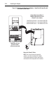
3. Open the drive cover.
4. Connect a cable to the network, and route it through the bottom of
the PowerFlex drive. (Refer to the LonMark Layers 1-6
Interoperability Guidelines, Appendix A “Cable Requirements for
the TP/FT-10 Channel.”)
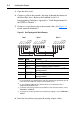
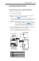
5. Connect a six-pin linear plug to the network cable. (See Figure 2.1
for the terminal definitions.)
Figure 2.1 Bus Topology with Shield Example
6. Insert the six-pin linear plug into the mating adapter socket.
Terminal Name Function
1 SHIELD
(1)
(1)
It is recommended to use shielded network cable. This shield must be grounded at one point
on the network via a 470K ohm, 1/4 watt, ≤ 10% metal film resistor.
Noise mitigation
(2)
(2)
For noise mitigation, LON trunk lines should not be run in close proximity to drive or
equipment power distribution feeds.
2 NET A Network connection, polarity insensitive
3 NET B Network connection, polarity insensitive
4 TERM BUS Connect to TERM COM for termination of Bus
(3)
topology networks.
(3)
To terminate a Bus Topology network (one termination at each end of the network), connect
TERM COM to TERM BUS.
5 TERM COM Termination common
6 TERM FT Connect to TERM COM for termination of Free
(4)
topology networks.
(4)
To terminate a Free Topology network (one termination per segment), connect TERM COM to
TERM FT.
Node 1 Node 2 Node "n"
SHIELD
NET A
NET B
TERM BUS
TERM COM
TERM FT
SHIELD
NET A
NET B
TERM BUS
TERM COM
TERM FT
SHIELD
NET A
NET B
TERM BUS
TERM COM
TERM FT