
Manual


Adapter Parameters B-5
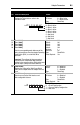
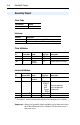
23 [DSI I/O Act]
Displays the Drives that are active in the
Multi-Drive mode.
Default: xxx0 0000
Bit Values: 0 = Drive Active
1 = Drive Inactive
Type: Read Only
Bit Definitions
0 = Drive 0 Active
1 = Drive 1 Active
2 = Drive 2 Active
3 = Drive 3 Active
4 = Drive 4 Active
5 = Not Used
6 = Not Used
7 = Not Used
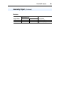
24
25
26
27
28
[Drv 0 Addr]
[Drv 1 Addr]
[Drv 2 Addr]
[Drv 3 Addr]
[Drv 4 Addr]
Sets the corresponding node addresses of the
daisy-chained drives when the adapter Operating
Mode Switch (SW1) is set for Multi-Drive
operation.
Important: The settings for these parameters
must match the Comm Node Addr parameter
settings in the respective drives. Each setting must
also be unique (no duplicate node address).
Default: 100
Default: 101
Default: 102
Default: 103
Default: 104
Minimum: 1
Maximum: 247
Type: Read/Write
Reset Required: Yes
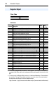
29 [Web Enable]
Displays the setting of the Web Pages Switch
(SW2) on the adapter when the adapter was last
reset.
Default: 0 = Disabled
Values: 0 = Disabled
1 = Enabled
Type: Read Only
30 [Web Features]
Sets the access to the Web interface and
Web-configurable features.
Default: xxxx xx11
Bit Values: 0 = Disabled
1 = Enabled
Type: Read/Write
Reset Required: No
Bit Definitions
0 = E-mail Configuration
1 = Process Display Configuration
2-7 = Not used
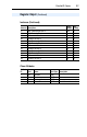
Parameter
No. Name and Description Details
Bit
Default
00000xxx
01234576
Bit
Default
11xxxxxx
01234576