
Owner manual

2 PowerFlex 755 with OEM Liquid Cooling AC Drive Transition Tube Kit - Frames 6 and 7
www.rockwellautomation.com
Amer
i
cas:
Rockwell
Automation, 1201 South
Second
Street,
Milwaukee,
WI 53204
-
2496
USA,
Tel:
(1)
414.382.2000, Fax: (1)
414.382.4444
Europe
/
Middle East
/
Africa:
Rockwell
Automati
on,
Pegasus
Park,
De Kleetlaan 12a,
1831 Diegem, Belgium,
Tel: (32) 2 663
0600, Fax: (32) 2 663
0640
Asia Pacific: Rockwell Automation, Level 14,
Core F,
Cyberport
3, 100
Cyberport Road,
Hong Kong,
Tel: (852) 2887 4788, Fax:
(852) 2508
1846
Power,
Control
and
Information Solutions
Headquarters
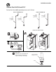
5
Outlet
Transition
Tube
Inlet
Transition
Tube
Outlet
Transition
Tube
Inlet
Transition
Tube
6
O-ring
Fitting with Face Seal
O-Ring
Backup Wrench
Swivel Nut
7
Frames 6 and 7
Install o-rings on the inlet and
outlet transition tube male fittings.
Verify that the o-rings are fully
seated in the fitting grooves.
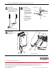
Frames 6 and 7
For each tube connection:
A. Place the transition tube
assembly against the
fitting body so that the flat
face of the brazed sleeve
is in full contact with the
o-ring.
B. Thread the nut by hand
onto the fitting body.
C. Using a backup wrench,
tighten to a torque of 81
N•m (60 lb•ft).
Frames 6 and 7
Installation completed as
shown at right.
(Frame 7 transition tubes shown)
(Frame 7 drive shown)
Publication 20GY-IN003B-EN-P – August 2011
Supersedes 20GY-IN003A-EN-P – June 2011 Copyright © 2011 Rockwell Automation, Inc. All rights reserved. Printed in USA.
*PN-121666*
PN-121666