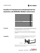
Installation Instructions PowerFlex 755 Transition Section and Splicing Kit for Floormount Drives and CENTERLINE 2100 Motor Control Centers Topic Page Introduction, Compatibility Introduction 1 Additional Resources 2 What the Kits Contain 2 Remove Power from All Equipment 3 Approximate Dimensions 4 Preparing the Transition Section 5 Joining Drive, Transition Section, and MCC 6 Left-side Kit Assembly 7 Right-side Kit Assembly 14 Specifications 25 This document explains the recommended
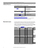
PowerFlex 755 Transition Section and Splicing Kit for Floor-mount Drives and CENTERLINE 2100 Motor Control Centers Additional Resources The following table lists publications that provide general PowerFlex 755 drives and CENTERLINE 2100 MCC related information.
PowerFlex 755 Transition Section and Splicing Kit for Floor-mount Drives and CENTERLINE 2100 Motor Control Centers Left-side Kits Follow all steps including the Left-side Kit Assembly sequence for 20 in. deep left-side-mount transition sections and the 15 in. deep left- or right-side-mount transition section. Right-side Kits Follow all steps including Right-side Kit Assembly sequence for 20 in. deep rightside-mount transition sections and the 15 in. deep left- or right-side-mount transition section.
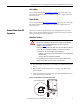
PowerFlex 755 Transition Section and Splicing Kit for Floor-mount Drives and CENTERLINE 2100 Motor Control Centers CENTERLINE 2100 MCC ATTENTION: De-energize all units before installing or removing. When installing or removing MCC units, when possible, deenergize, lockout, and tag-out all sources of power to the MCC. ATTENTION: De-energize all power sources to the motor control center before joining and splicing with the drive. Failure to de-energize all power sources can result in severe injury or death.
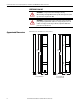
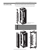
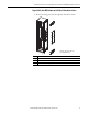
PowerFlex 755 Transition Section and Splicing Kit for Floor-mount Drives and CENTERLINE 2100 Motor Control Centers Preparing the Transition Section 1. Remove and discard the four shipping plates ➊. 2. Remove the masking from the ground terminals ➋. MCC Columns with Mounting Channels 3. Remove the spacer ➌ on the side of the transition section that will attach to the MCC column. MCC Columns without Mounting Channels 3. Remove the mounting channels ➍ from the transition section. ➊ x4 ➊ ➋ x4 ➌ ➍ No.
PowerFlex 755 Transition Section and Splicing Kit for Floor-mount Drives and CENTERLINE 2100 Motor Control Centers Joining Drive, Transition Section, and MCC Physical restrictions at your installation may not allow the following sequence to be followed exactly as stated. Step 1: Remove Drive Assembly The PowerFlex 755 drive assembly must be removed to access side panels and horizontal bus bars.
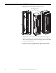
PowerFlex 755 Transition Section and Splicing Kit for Floor-mount Drives and CENTERLINE 2100 Motor Control Centers Left-side Kit Assembly Step 3 (Left): Join Transition Section to Left Side of Drive Cabinet 1. Remove panels from the left side of the PowerFlex 755 drive cabinet. ➊ ➋ ➌ ➋ ➊ No. Description ➊ Top and bottom rear-wireway panels. ➋ Top and bottom PE bus-bar access panels. ➌ Main horizontal bus-bar access panel. Cabinet door and internal components omitted for clarity. 2.
PowerFlex 755 Transition Section and Splicing Kit for Floor-mount Drives and CENTERLINE 2100 Motor Control Centers 3. Bring the transition section and drive cabinet together. 4. Pass the M6 x 16 mm hex-head thread-forming screws from inside the transition section through the joining holes and engage the screws with the ➊ holes in the drive cabinet. 5. Make sure cabinets are level and pushed together tightly. 6. Tighten the screws in a uniform pattern.
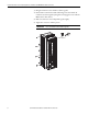
PowerFlex 755 Transition Section and Splicing Kit for Floor-mount Drives and CENTERLINE 2100 Motor Control Centers Step 4 (Left): Join MCC Column to Left Side of Transition Section 1. Remove the closing plates from the right side of the MCC column. ➋ ➊ ➌ ➋ ➊ No. Description ➊ Top and bottom front-wireway closing plates. ➋ Top and bottom rear-wireway closing plates. ➌ Main horizontal bus-bar closing plates.
PowerFlex 755 Transition Section and Splicing Kit for Floor-mount Drives and CENTERLINE 2100 Motor Control Centers 2. Align the MCC column with the left transition section. MCC side of transition section ➊ ➊ ➊ ➋ ➊ ➊ ➊ 3. Bring the MCC column, transition section, and drive cabinet together. 4. Pass the 1/4-20 x 0.5 in. hex-head thread-forming screws from inside the MCC column through the joining holes and engage the screws with the ➊ holes in the transition section. 5. Pass the 1/4-20 x 1 in.
PowerFlex 755 Transition Section and Splicing Kit for Floor-mount Drives and CENTERLINE 2100 Motor Control Centers 6. Make sure cabinets are level and pushed together tightly. 7. Tighten the screws in a uniform pattern. IMPORTANT Do not use hardware to draw cabinets together. 1/4-20 6.
PowerFlex 755 Transition Section and Splicing Kit for Floor-mount Drives and CENTERLINE 2100 Motor Control Centers Step 5 (Left): Join PE Bus Bar and Grounding Bracket 1. Align the protective earth (PE) conductor splicing hardware with the transition section grounding bracket. 2. Insert and tighten the 1/4-20 x 1 in. screws. IMPORTANT Do not grease or lubricate hardware. 1/4-20 x 1 in. 7.
PowerFlex 755 Transition Section and Splicing Kit for Floor-mount Drives and CENTERLINE 2100 Motor Control Centers Step 6 (Left): Connect PE Splicing Cables 1. Pass the cables through the bottom wireway openings. 2. Connect the PE splicing cables between the MCC and drive PE bus bars. 1/4-20 x 1 in. ➊ 1/4-20 x 1.25 in. ➋ 1/4-20 x 1 in. ➌ 1/4-20 7.3 N•m (65 lb•in) 10 mm No. Description ➊ 1200A with 25.4 mm (1 in.) bus bar. Requires two splice cables. ➋ 2000A with 25.4 mm (1 in.) bus bar.
PowerFlex 755 Transition Section and Splicing Kit for Floor-mount Drives and CENTERLINE 2100 Motor Control Centers Right-side Kit Assembly Step 3 (Right): Join Transition Section to Left Side of MCC Column 1. Remove the closing plates from the left side of the MCC column. ➋ ➊ ➌ ➋ Unit doors, support pans, and access covers omitted for clarity. ➊ No. Description ➊ Top and bottom front-wireway closing plates. ➋ Top and bottom rear-wireway closing plates. ➌ Main horizontal bus-bar closing plates.
PowerFlex 755 Transition Section and Splicing Kit for Floor-mount Drives and CENTERLINE 2100 Motor Control Centers 3. Bring the transition section and MCC column together. 4. Pass the 1/4-20 x 0.5 in. hex-head thread-forming screws from inside the transition section through the joining holes and engage the screws with the ➊ holes in the MCC column. 5. Pass the 1/4-20 x 1 in. screw from inside the MCC column through the transition section joining hole ➋ and secure with the 1/4-20 steel nut. 6.
PowerFlex 755 Transition Section and Splicing Kit for Floor-mount Drives and CENTERLINE 2100 Motor Control Centers Step 4 (Right): Join PE Bus Bar and Grounding Bracket 1. Align the protective earth (PE) conductor splicing hardware with the transition section grounding bracket. 2. Insert and tighten the 1/4-20 x 1 in. screws. IMPORTANT Do not grease or lubricate hardware. 1/4-20 x 1 in. 7.
PowerFlex 755 Transition Section and Splicing Kit for Floor-mount Drives and CENTERLINE 2100 Motor Control Centers Step 5 (Right): Join Drive Cabinet to Left Side of Transition Section 1. Remove panels from the right side of the PowerFlex 755 drive cabinet. ➊ ➋ ➌ ➋ ➊ No. Description ➊ Top and bottom rear-wireway panels. ➋ Top and bottom PE bus-bar access panels. ➌ Main horizontal bus-bar access panel.
PowerFlex 755 Transition Section and Splicing Kit for Floor-mount Drives and CENTERLINE 2100 Motor Control Centers 2. Align the right transition section with the drive cabinet. ➊ ➊ ➊ ➊ ➊ ➊ ➊ ➊ 3. Bring the transition section, MCC column, and drive cabinet together. 4. Pass the M6 x 16 mm hex-head thread-forming screws from inside the drive cabinet through the joining holes and engage the screws with the ➊ holes in the transition section.
PowerFlex 755 Transition Section and Splicing Kit for Floor-mount Drives and CENTERLINE 2100 Motor Control Centers 5. Make sure cabinets are level and pushed together tightly. 6. Tighten the screws in a uniform pattern. IMPORTANT Do not use hardware to draw cabinets together. M6 6.2 N•m (55 lb•in) 10 mm Step 6 (Right): Connect PE Splicing Cables 1. Pass the cables through the bottom wireway openings. 2. Connect the PE splicing cables between the MCC and drive PE bus bars. 1/4-20 x 1 in. ➊ 1/4-20 x 1.
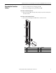
PowerFlex 755 Transition Section and Splicing Kit for Floor-mount Drives and CENTERLINE 2100 Motor Control Centers Step 7: Join Horizontal Bus and Splicing Bars Splicing kits will contain either two or four sets of hardware per splice bar, depending on the current rating of the horizontal bus. Assemble hardware as depicted in Figure 2 and uniformly tighten splice kit hardware to the final torque listed in Table 1.
PowerFlex 755 Transition Section and Splicing Kit for Floor-mount Drives and CENTERLINE 2100 Motor Control Centers Left-side Standard Bus-bar Splice Kits Standard Bus-bar Position Figure 3 - 1200A (Kit No. 20-750-XBUS-LHNB/LLNB-1200) - Standard Bus-bar Position 3/8-16 x 1.38 in. PowerFlex Drive Horizontal Bus MCC Horizontal Bus Front Figure 4 - 2000A (Kit No. 20-750-XBUS-LHNB/LLNB-2000) - Standard Bus-bar Position 3/8-16 x 2.25 in.
PowerFlex 755 Transition Section and Splicing Kit for Floor-mount Drives and CENTERLINE 2100 Motor Control Centers Left-side Bumped-Back Bus-bar Splice Kits Bumped-Back Bus-bar Position Figure 6 - 1200A (Kit No. 20-750-XBUS-LHBB/LLBB-1200) - Bumped-Back Bus-bar Position 3/8-16 x 1.38 in. PowerFlex Drive Horizontal Bus MCC Horizontal Bus Front Figure 7 - 2000A (Kit No. 20-750-XBUS-LHBB/LLBB-2000) - Bumped-Back Bus-bar Position 3/8-16 x 2.25 in.
PowerFlex 755 Transition Section and Splicing Kit for Floor-mount Drives and CENTERLINE 2100 Motor Control Centers Right-side Standard Bus-bar Splice Kits Standard Bus-bar Position Figure 9 - 1200A (Kit No. 20-750-XBUS-RHNB/RLNB-1200) - Standard Bus-bar Position 3/8-16 x 1.38 in. MCC Horizontal Bus PowerFlex Drive Horizontal Bus Front Figure 10 - 2000A (Kit No. 20-750-XBUS-RHNB/RLNB-2000) - Standard Bus-bar Position 3/8-16 x 2.25 in.
PowerFlex 755 Transition Section and Splicing Kit for Floor-mount Drives and CENTERLINE 2100 Motor Control Centers Right-side Bumped-Back Bus-bar Splice Kits Bumped-Back Bus-bar Position Figure 12 - 1200A (Kit No. 20-750-XBUS-RHBB/RLBB-1200) - Bumped-Back Bus-bar Position 3/8-16 x 1.38 in. MCC Horizontal Bus PowerFlex Drive Horizontal Bus Front Figure 13 - 2000A (Kit No. 20-750-XBUS-RHBB/RLBB-2000) - Bumped-Back Bus-bar Position 3/8-16 x 2.25 in.
PowerFlex 755 Transition Section and Splicing Kit for Floor-mount Drives and CENTERLINE 2100 Motor Control Centers Specifications Tighten all bus connections with a torque wrench and socket according to intervals established by your maintenance policy. If a torque wrench is not available, tighten until the conical spring washer is flat. Do not grease or lubricate the hardware. Table 1 - Torque Requirements Description Hardware Torque Transition section to drive cabinet joining screws M6 6.
Rockwell Automation Support Rockwell Automation provides technical information on the Web to assist you in using its products. At http://www.rockwellautomation.com/support, you can find technical manuals, technical and application notes, sample code and links to software service packs, and a MySupport feature that you can customize to make the best use of these tools. You can also visit our Knowledgebase at http://www.rockwellautomation.