
Reference Manual Owner's manual

Rockwell Automation Publication 750-RM001F-EN-P - February 2012 97
Chapter 8
Slave Modes for Multi-axis Cascaded Systems
Introduction
This chapter describes the slave modes of safety operation and wiring examples of
cascaded multi-axis configurations.
Cascaded Configurations
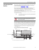
Use the P20 [Cascaded Config] parameter to define the safety option’s position
in the system as Single Unit (Single), Cascaded First Unit (Multi First), Cascaded
Middle Unit (Multi Mid), or Cascaded Last Unit (Multi Last). Only the middle
or last safety option in a multi-axis system can be configured for slave modes.
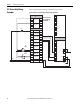
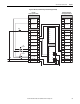
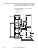
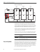
For cascaded safety options, connect the safety switches to the safety inputs
(SS_In, SLS_In, DM_In, ESM_In, and LM_In) of the first (master) axis only.
Each feedback for Safe Stop functions are connected to their respective axis. The
inputs are cascaded from one safety option to the next by connecting the outputs
from the previous safety option to the inputs of the next safety option.
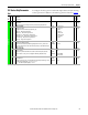
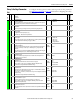
Topic Page
Cascaded Configurations 97
Slave, Safe Stop Mode 98
Slave, Safe Stop Parameter List 99
Slave, Safe Stop Wiring Examples 101
Slave, Safe Limited Speed Mode 104
Slave, Safe Limited Speed Parameters 104
Slave, Safe Limited Speed Wiring Examples 105
Slave, Safe Limited Speed Status Only Mode 107
Slave, Safe Limited Speed Status Only Parameter List 107
Slave, Safe Limited Speed Status Only Wiring Examples 108
Multi-axis Connections 110