
Reference Manual Owner's manual

Rockwell Automation Publication 750-RM001F-EN-P - February 2012 41
Speed Monitoring I/O Signals Chapter 4
Outputs
The safety option has three safety control outputs. The outputs have various
output current capabilities, depending on function.
See the specifications in Appendix A
to verify your power requirements.
Safe Stop Output (SS_Out)
The safe state for this signal is OFF.
These outputs are typically used in multi-axis applications. In multi-axis
applications, you can use these outputs to daisy-chain the master safety option to
a slave.
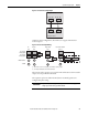
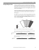
For SS_Out to SS_In cascaded signals, the interface is a dual-channel sourcing
solid-state safety output connected to a dual-channel safety input configured as
OSSD. The outputs are pulse-tested when the P72 [SS Out Mode] parameter is
configured for pulse-testing.
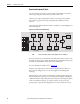
Figure 6 - SS_Out to SS_In Connections for Multi-axis Applications
For more information on multi-axis configurations, see Cascaded Configurations
starting on page 97
.
Alternately, the first SS_Out output may be used to signal a programmable logic
controller (PLC) that a Safe Stop has been requested.
If the SS_In is ON (closed) and a successful Safe Stop Reset is performed, the
SS_Out output is turned ON. If Lock Monitoring is not enabled or the door
control logic state is Unlock, the SS_Out signal turns ON immediately when the
SS_In turns ON. If Lock Monitoring is enabled, and the door control logic state
is Lock, the SS_Out signal is not turned ON until the door has been locked by
using the DC_Out signal and the LM_In input has been verified as ON.
IMPORTANT
If you disable pulse-testing on this output, the achievable SIL, Category, and PL
ratings of your entire safety system are reduced.
Safety Option (Master)
SS_OUT_CH0
SS_OUT_CH1
Safety Option (Slave)
SS_IN_CH0
SS_IN_CH1
TB2-S12 and TB2-S22 are
configured as 2 OSSD 3s inputs.
TB2-34
TB2-S12
TB2-44
TB2-S22