
Reference Manual Owner's manual


32 Rockwell Automation Publication 750-RM001F-EN-P - February 2012
Chapter 3 Installation and Wiring
Installation in Frame 8 and
Larger Drives
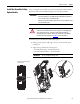
When installed in a Frame 8 or larger drive, an EMC Core Kit, catalog number
20-750-EMCSSM1-F8, is required.
Terminal Connections
Shielded cable is required.
Prepare wires for termination on the safety option module with a 6 mm (0.25 in.)
strip length.
Tighten all terminal screws firmly and recheck them after all connections have
been made. Recommended terminal screw torque is 0.2 N•m (1.8 lb•in).
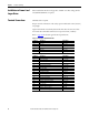
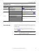
Refer to page 161
for the I/O signal electrical specifications.
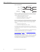
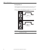
Table 2 - Safety Option Module TB1 Pinouts
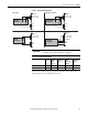
Table 3 - Safety Option Module TB2 Pinouts
Terminal Description Signal Name
S11 Pulse Test TEST_OUT_0
S11 Pulse Test TEST_OUT_0
S11 Pulse Test TEST_OUT_0
S21 Pulse Test TEST_OUT_1
S21 Pulse Test TEST_OUT_1
S21 Pulse Test TEST_OUT_1
Terminal Description Signal Name
S34 Reset Input RESET_IN
52 Door Control Output DC_OUT_CH1
51 Door Control Output DC_OUT_CH0
78 Safe Limited Speed Output SLS_OUT_CH1
68 Safe Limited Speed Output SLS_OUT_CH0
44 Safe Stop Output SS_OUT_CH1
34 Safe Stop Output SS_OUT_CH0
X42 Lock Monitoring Input LM_IN_CH1
X32 Lock Monitoring Input LM_IN_CH0
S42 Door Monitoring Input DM_IN_CH1
S32 Door Monitoring Input DM_IN_CH0
S62 Safe Limited Speed Input SLS_IN_CH1
S52 Safe Limited Speed Input SLS_IN_CH0
S82 Enabling Switch Monitoring Input ESM_IN_CH1
S72 Enabling Switch Monitoring Input ESM_IN_CH0
S22 Safe Stop Input SS_IN_CH1
S12 Safe Stop Input SS_IN_CH0
A2 Common, customer supplied 24V_COM
A1 +24V DC, customer supplied +24V