
Reference Manual Owner's manual

Rockwell Automation Publication 750-RM001F-EN-P - February 2012 145
Configuration Examples Chapter 11
12. Enter 5, 9, or 12V to monitor voltage in accordance with the encoder’s
specifications, or enter 0 (default) to disable encoder voltage monitoring.
13. Choose the P42 [Direction Mon] parameter.
14. Set the P42 [Direction Mon] parameter value to 2, to set up the normal
monitored direction as Negative Always.
15. Choose the P43 [Direction Tol] parameter.
16. Enter value between 0…65,535 degrees based on the encoder’s
specifications.
The default value is 10 degrees.
This sets the position limit tolerated in the wrong direction when Safe
Direction Monitoring is enabled. Entering 360 equals one revolution in
the forward direction before a Direction Fault occurs.
17. Go to the next section to set the parameters found in the Stop parameters
group.
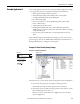
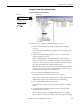
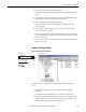
Example 2: Stop Group Settings
Figure 56 - Stop Group Parameters
Follow these steps to configure the Stop operation of the safety option.
1. From the Stop group, choose the P44 [Safe Stop Input] parameter.
2. Set the P44 [Safe Stop Input] parameter value to 1 (default) for 2NC
(dual-channel equivalent) operation.
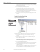
TIP
The P33 [Fbk 1 Speed] parameter displays the output speed of the encoder as a
value between
-214,748,364.8…214,748,364.8 rpm based on the encoder’s configuration.
You do not need to enter a setting or value for this parameter.
Port 04: Param File-Group
FILE: Parameter Groups
Safe Stop Input
ESC
AUTONot Enabled
0.000 Hz
F
GROUP: Stop
Safe Stop Type
Stop Mon Delay
HIM Screen Software Screen