
Reference Manual Owner's manual

Rockwell Automation Publication 750-RM001F-EN-P - February 2012 141
Configuration Examples Chapter 11
Example Application 2
This example application shows how to change the default configuration settings
to set up the safety option for an application with these basic parameters:
• Safe Stop (SS) enabled with an E-stop button.
• Safe Limited Speed (SLS) initiated with a 2NC contact switch.
• A configured Safe Maximum Speed (SMS) limit.
• Door Monitoring (DM)
• Door Control (DC) to control a guardlocking switch (TLS-3 GD2,
Power to Release style).
• A Reset button with 1 NO contact.
• Enabling Switch (ESM) with 2NC contacts. Hold the switch in the
middle position to access the machine for maintenance while it is running
at Safe Limited Speed.
• One encoder connected with Sin/Cos output signal and resolution of
1024.
Each of the following sections describes the settings you need to enter for each
parameter group. You can use a HIM module, DriveExplorer, DriveExecutive, or
RSLogix 5000 software to configure the safety option.
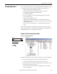
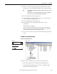
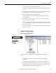
Example 2: Initial Security Group Settings
Figure 53 - Security Group Parameters
Follow these steps to put the safety option into Program mode for configuration.
1. From the Security group, choose the P5 [Lock State] parameter.
The default value of the Lock State parameter is 0 or unlocked.
2. If the safety option is locked (Lock State parameter value equals 1), set the
P5 [Lock State] parameter value to 0.
If an error occurs, a password has been configured to protect the safety
option configuration.
Port 04: Param File-Group
FILE: Parameter Groups
Password
ESC
AUTONot Enabled
0.000 Hz
F
GROUP: Security
Lock State
Operating Mode
HIM Screen Software Screen