
Manual

Rockwell Automation Publication 750-IN001N-EN-P - April 2014 275
PowerFlex 750-Series AC Drives
Control Pod Cable Routing
Floor Mount Frames 8…10
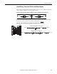
Supports, clips, and cable ties are provided to help route cabling inside the control pod.
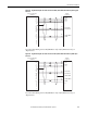
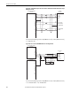
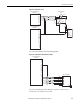
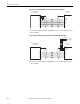
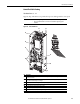
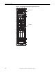
Figure 139 - Control POD Detail
IMPORTANT
• When routing cabling into the control POD, do not block the cooling fan outlet.
• Do not ground shield wires to inner sheet metal bucket supporting option
modules.
No. Description
➊ I/O Signal shield termination points. Use M4 screws and ring terminals provided to tie together and terminate
drain wires and shields.
➋ Ground shield wires to outer sheet metal bucket. Strip cable insulation 25 mm (1 in.) to expose braid. Attach cable
ties around shield and through slots. Pull tight.
➌ Attachment points for cable management devices provided (6 places).
➍ Cable support ladder.
➎ Fan outlet. Keep clear to help ensure proper cooling.
➏ Control cable entry and routing.
➐ Human Interface Module (HIM) cable entry and routing.
➑ Shield termination points.
➋
➌
➍
➎
➏
➏
➑
➐
➊
➐