
Manual

252 Rockwell Automation Publication 750-IN001N-EN-P - April 2014
PowerFlex 750-Series AC Drives
Dual-Port EtherNet/IP Option Module
For complete information on the Dual-Port EtherNet/IP Option Module, refer
to the PowerFlex 20-750-ENETR Dual-Port EtherNet/IP Option Module User
Manual, publication 750COM-UM008.
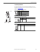
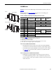
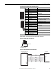
Table 73 - EtherNet Option Module LED Indication
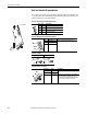
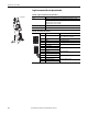
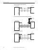
Table 74 - EtherNet Option Module Rotary Switches
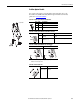
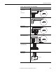
Table 75 - J4 Jumper
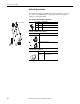
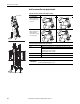
Table 76 - Ethernet Connectors
20-750-ENETR
LED Name Description
➊ PORT DPI Connection Status
➋ MOD Option Module Status
➌ NET A Network Port 1 Status
➍ NET B Network Port 2 Status
Switch Name Description
➊ HUNDREDS Switch Sets the node address of the option module.
➋ TENS Switch
➌ ONES Switch
Adapter Mode Tap Mode
Connector Name Description
➊ ENET1 Ethernet RJ45 connection to the network.
➋ ENET2
➌ ENET3 (DEVICE) Connection for the short Ethernet cable (provided
with option module) to the Ethernet port on the
PowerFlex 755 drive embedded EtherNet/IP adapter.
This is used only for CIP Motion data transfer.
➊
➋
➌
➍
➊
➋
➌
ADPTR
J4
TAP
MODE
ADPTR
J4
TAP
MODE
➊
➋
➌