Installation Instructions Original Instructions PowerFlex® 750-Series AC Drives Introduction This document explains the 5 BASIC STEPS for mechanical installation and for connecting incoming power, the motor, and basic I/O to the PowerFlex 750Series Adjustable Frequency AC drive. The information provided is intended for qualified installers only.
PowerFlex 750-Series AC Drives PowerFlex 750-Series AC Drives Table of Contents Additional Resources . . . . . . . . . . . . . . . . . . . . . . . . . . . . . . . . . . . . . . . . . . . . . . . . . . . . . .5 Commonly Used Tools Installation and Service Tools . . . . . . . . . . . . . . . . . . . . . . . . . . . . . . . . . . . . . . . . . . . . . .6 Step 1: Read the General Precautions Qualified Personnel . . . . . . . . . . . . . . . . . . . . . . . . . . . . . . . . . . . . . . . . . . . . . . . . .
PowerFlex 750-Series AC Drives Motor Considerations . . . . . . . . . . . . . . . . . . . . . . . . . . . . . . . . . . . . . . . . . . . . . . . . . . 133 Terminal Block Specifications . . . . . . . . . . . . . . . . . . . . . . . . . . . . . . . . . . . . . . . . . . . 133 Three-Phase Terminal Locations . . . . . . . . . . . . . . . . . . . . . . . . . . . . . . . . . . . . . . . . 134 Wall Mount Frames 1…7 AC Input Power Terminals . . . . . . . . . . . . . . . . . . . . . .
PowerFlex 750-Series AC Drives 22-Series I/O Wiring Examples . . . . . . . . . . . . . . . . . . . . . . . . . . . . . . . . . . . . . . . . . 241 Safe Speed Monitor Option Module . . . . . . . . . . . . . . . . . . . . . . . . . . . . . . . . . . . . . 247 Auxiliary Power Supply Option Module . . . . . . . . . . . . . . . . . . . . . . . . . . . . . . . . . 249 DeviceNet Option Module . . . . . . . . . . . . . . . . . . . . . . . . . . . . . . . . . . . . . . . . . . . . . 250 ControlNet Option Module . .
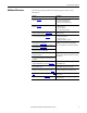
PowerFlex 750-Series AC Drives Additional Resources The following table lists publications that provide general drive related information.
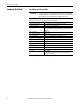
PowerFlex 750-Series AC Drives Commonly Used Tools Installation and Service Tools IMPORTANT Care must be taken to be sure that tools and/or hardware components do not fall into open drive assemblies. Do not energize the drive unless all loose tools and/or hardware components have been removed from the drive assemblies and enclosure. This list covers the tools needed for drive installation.
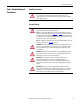
PowerFlex 750-Series AC Drives Step 1: Read the General Precautions Qualified Personnel ATTENTION: Only qualified personnel familiar with adjustable frequency AC drives and associated machinery should plan or implement the installation, start-up and subsequent maintenance of the system. Failure to comply may result in personal injury and/or equipment damage.
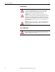
PowerFlex 750-Series AC Drives Product Safety ATTENTION: An incorrectly applied or installed drive can result in component damage or a reduction in product life. Wiring or application errors such as under sizing the motor, incorrect or inadequate AC supply, a corrosive environment, or excessive surrounding air temperatures may result in malfunction of the system. ATTENTION: This drive contains ESD (Electrostatic Discharge) sensitive parts and assemblies.
PowerFlex 750-Series AC Drives Step 2: Prepare for Installation Catalog Number Explanation 1…3 4 5 6 7 8…10 11 12 13 14 15 16 17 18 20G 1 A N D 248 A A 0 N N N N N a b c d e f1…f4 g h i a Code 20F 20G 21G Drive Type PowerFlex 753 PowerFlex 755 PowerFlex 755 Drive with Options Cabinet Options (21G) e Frames 1…7 1…10 8…10 Voltage Rating Voltage Code b C 400V AC/540V DC D 480V AC/650V DC E 600V AC/810V DC F 690V AC/932V DC (not UL listed) Future Use f1 f
PowerFlex 750-Series AC Drives Catalog Number Explanation (continued) 1…3 4 5 6 7 8…10 11 12 13 14 15 16 17 18 20G 1 A N D 248 A A 0 N N N N N a b c d e f1…f4 g h i f3 Code Amps Hp 1P7 1.7 1 2P7 2.7 2 3P9 3.9 3 6P1 6.1 5 9P0 9 7.
PowerFlex 750-Series AC Drives Wall Mount Frames 1…7 Drive Rating Cross-References Nameplate 1: Specifications and Custom Catalog Number representing options installed at factory. See Nameplate 2 (Located behind HIM) for equivalent base catalog number and separate options Cat No.
PowerFlex 750-Series AC Drives Floor Mount Frames 8…10 Drive Rating Cross-References ➋ ➋ ➊ Input Voltage & ND Amp Rating Enclosure Code Nameplate 1: Specifications and Custom Catalog Number representing options installed at factory.
PowerFlex 750-Series AC Drives CE Conformity Compliance with the Low Voltage Directive and Electromagnetic Compatibility Directive has been demonstrated using harmonized European Norm (EN) standards which are referenced by the Official Journal of the European Union. PowerFlex 750-Series drives comply with the EN standards listed below when installed according to this PowerFlex 750-Series AC Drive Installation Instructions. EU Declarations of Conformity are available online at: www.rockwellautomation.
PowerFlex 750-Series AC Drives • PowerFlex 750-Series drives generate harmonic current emissions on the AC supply system. When operated on a public low-voltage network it is the responsibility of the installer or user to ensure that applicable requirements of the distribution network operator have been met. Consultation with the network operator and Rockwell Automation may be necessary.
PowerFlex 750-Series AC Drives All Drive Frames: • Drives provided in the IP54, NEMA/UL Type 12 enclosure are compliant with the CE LV Directive when installed in pollution degree 1…4 environments. All other enclosure types must be installed in a pollution degree 1 or 2 environment to be compliant with the CE LV Directive. Characteristics of the different pollution degree ratings are provided in the PowerFlex 750-Series AC Drives Technical Data, publication 750-TD001.
PowerFlex 750-Series AC Drives Installation Requirements Related to EN 61800-3 and the EMC Directive • The drive must be earthed (grounded) as described in Step 4: Power Wiring on page 131. • Output power wiring to the motor must employ cable with a braided shield providing 75% or greater coverage, or the cables must be housed in metal conduit, or equivalent shielding must be provided. Continuous shielding must be provided from the drive enclosure to the motor enclosure.
PowerFlex 750-Series AC Drives Table 1 - PowerFlex 750-Series 400/480V Input Drives RF Emission Compliance and Installation Requirements Drive Frame Catalog Number Wall Mount Frame 1 20F11xx2P1…20F11xx015 20G11xx2P1…20G11xx015 Wall Mount Frame 2 20F11xx2P1…20F11xx022 20G11xx2P1…20G11xx022 Wall Mount Frame 3 20F11xx030…20F11xx043 20G11xx030…20G11xx043 Wall Mount Frame 4 20F11xx060…20F11xx072 20G11xx060…20G11xx072 Wall Mount Frame 5 20F11xx085…20F11xx104 20G11xx085…20G11xx104 Wall Mount Frame 6 20F11xx1
PowerFlex 750-Series AC Drives Table 2 - PowerFlex 750-Series 600/690V Input Drives RF Emission Compliance and Installation Requirements Drive Frame Catalog Number Wall Mount Frame 3: 600V (3 Hp and higher.
PowerFlex 750-Series AC Drives Access Panels, Covers, and Doors Figure 1 - Enclosure Code R (IP20, NEMA/UL Open Type) Wall Mount Frame 1 Figure 2 - Enclosure Code N (IP20, NEMA/UL Open Type) Wall Mount Frames 2…5 Rockwell Automation Publication 750-IN001N-EN-P - April 2014 19
PowerFlex 750-Series AC Drives Figure 3 - Enclosure Code G (IP54, NEMA/UL Type 12) Wall Mount Frames 2…5 2x: M4 X 0.7 When cover is replaced: • Recommended torque (screws and nuts) = 0.68 N•m (6.0 lb•in) • Recommended screwdriver = 6.4 mm (0.25 in.) flat or T20 Hexalobular • Recommended hex socket = 7 mm Figure 4 - Enclosure Code N (IP00, NEMA/UL Open Type) Wall Mount Frames 6 and 7 90° When cover is replaced: • Recommended screwdriver = 9.5 mm (0.375 in.
PowerFlex 750-Series AC Drives Figure 5 - Enclosure Code N (IP00, NEMA/UL Open Type) Wall Mount Frames 6 and 7 Access Door When door is replaced: • Recommended screwdriver = 6.4 mm (0.25 in.
PowerFlex 750-Series AC Drives Figure 6 - Floor Mount Frames 8 and Larger Cabinet Access Door (All Enclosure Types) 90° To release or secure door: • Recommended screwdriver = 9.5 mm (0.375 in.
PowerFlex 750-Series AC Drives Figure 7 - Floor Mount Drive Assembly Access Panels - All Enclosure Types (IP20, NEMA/UL Type 1 Shown) ➌ ➊ ➍ ➋ ➎ No.
PowerFlex 750-Series AC Drives Figure 8 - Floor Mount Cabinet Options Bay Access Door Floor Mount Frame 8 - IP20, NEMA/UL Type 1 Floor Mount Frame 9 - IP54, NEMA 12 To release or secure door: • Recommended screwdriver = 9.5 mm (0.375 in.
PowerFlex 750-Series AC Drives Figure 9 - Full Cabinet Options Bay Guard - Floor Mount Frame 8 To remove the full bay guard, loosen the ten M5 screws. It is not necessary to remove these screws. When the full bay guard is replaced: • Recommended torque = 2.8 N•m (25.
PowerFlex 750-Series AC Drives Figure 10 - Full Cabinet Options Bay Guard Floor Mount Frame 9 To remove the full bay guard, loosen the ten M5 screws. It is not necessary to remove these screws. When the full bay guard is replaced: • Recommended torque = 2.8 N•m (25.
PowerFlex 750-Series AC Drives Minimum Clearances Specified vertical clearance requirements (indicated in Figure 11) are intended to be from the drive to the closest object that may restrict airflow through the drive heat sink and chassis. The drive must be mounted in a vertical orientation as shown and must make full contact with the mounting surface. Do not use standoffs or spacers. In addition, inlet air temperature must not exceed the product specification.
PowerFlex 750-Series AC Drives Mounting Considerations Wall Mount Frames 1…7 • Mount the drive upright on a flat, vertical and level surface. • Verify the drive is in full contact with the mounting surface as depicted in Figure 11. Floor Mount Frames 8…10 • Install the drive upright on a flat and level surface. • Verify the drive cabinet is square, vertical, and stable. • Verify the filter and debris screens are installed.
PowerFlex 750-Series AC Drives Step 3: Lift and Mount the Drive Drive Weights All lifting equipment and lifting components (hooks, bolts, lifts, slings, chains, and so forth) must be properly sized and rated to safely lift and hold the weight of the drive while mounting. ATTENTION: To guard against possible personal injury and/or equipment damage… • Inspect all lifting hardware for proper attachment before lifting drive.
PowerFlex 750-Series AC Drives Recommended Mounting Hardware Frame Size Wall Mount Floor Mount IMPORTANT 30 Fastener Size 1 2 3 4 5 6 7 8 9 10 Notes M6 (#10 or #12) M6 (#12) M8 (5/16 in.) M12 (1/2 in.) Property Class 8.8 (Minimum) Mounting hardware is provided with enclosure type F (Flange mount) drives. The hardware supplied must be used to meet the enclosure rating.
PowerFlex 750-Series AC Drives Attach Lifting Hardware Figure 13 - Rigging Geometry >1/2 A <45° A >1/2 A <45° A Enclosure Code F Wall Mount Frame 6 Lifting Points – 2 Places Wall Mount Frame 7 Lifting Points – 4 Places Rockwell Automation Publication 750-IN001N-EN-P - April 2014 31
PowerFlex 750-Series AC Drives Enclosure Code N Wall Mount Frame 6 Lifting Points – 6 Places Wall Mount Frame 7 Lifting Points – 8 Places Enclosure Code G Wall Mount Frames 6 and 7 Lifting Points – 4 Places 32 Rockwell Automation Publication 750-IN001N-EN-P - April 2014
PowerFlex 750-Series AC Drives Open Type Drive (Removed From Cabinet) Floor Mount Drive Assembly – IP00, NEMA/UL Type Open Drive Lifting Points – 2 Places Enclosure Codes B and L Floor Mount Frame 8 Lifting Points – 2 Places Rockwell Automation Publication 750-IN001N-EN-P - April 2014 33
PowerFlex 750-Series AC Drives Floor Mount Frames 9 and 10 Lifting Points – 2 Places Enclosure Codes J, K, and Y Floor Mount Frame 9 with Cabinet Options Bay Lifting Points – 2 Places 34 Rockwell Automation Publication 750-IN001N-EN-P - April 2014
PowerFlex 750-Series AC Drives Release Floor Mount Drive Cabinet From Shipping Skid Remove the bolts fastening a vertically oriented drive cabinet to the shipping skid and lift. <45° >1/2 A A <45° >1/2 A A M10 x 25 17 mm Remove the shipping crate that encloses a horizontally oriented drive cabinet on the shipping skid and lift.
PowerFlex 750-Series AC Drives Remove Drive Cabinet Lifting Angle After the drive cabinet is in its final position, remove the lifting angle. M12 67.
PowerFlex 750-Series AC Drives Install IP20, NEMA/UL Type 1 Debris Screen or Optional Exhaust Hood IP20, NEMA/UL Type 1 drives are equipped with a top mounted debris screen. An optional exhaust hood is also available as a kit (20-750-HOOD1-F8). 1. Install the supplied debris screen over the exhaust vent. or Install the optional exhaust hood with the grill facing the front of the drive. 2. Secure with the four screws provided. T25 4.
PowerFlex 750-Series AC Drives Install Floor Mount Drive with Power Options Bay and Wiring Bay Frame 9 drives configured with both the power options bay and wiring bay ship in two sections. The following procedure describes how to join the wiring bay to the power options bay. 1. Remove external wrapping, bus bar cover, and locate joining hardware. Joining hardware is shipped with the wiring bay.
PowerFlex 750-Series AC Drives 3. Attach lifting hardware to the drive assembly. Follow lifting instructions and precautions beginning on page 29. 4. Locate the factory-assembled drive cabinets and power options bay in its final position. 5. Remove and discard the seven M8 sealing screws from the right side of the power options bay.
PowerFlex 750-Series AC Drives Position the Wiring Bay 6. Remove and discard the screws holding the protective panel against the left side of the wiring bay. M6 x 13 10 mm IP54, NEMA 12 Enclosure Rating Shown 7. Remove and discard the protective panel.
PowerFlex 750-Series AC Drives 8. Remove and discard the wiring bay inner panels covering the ends of the bus bars. Wiring Bay M6 x 25 T30 9. Release the wiring bay from the shipping skid. The shipping angles on the left side of the cabinet can be left in place to assist with alignment in step 11. Remove the shipping angles after cabinets are aligned and joined. M8 x 16 3/8 in. 13 mm 9/16 in.
PowerFlex 750-Series AC Drives 10. Align the wiring bay with power options bay. 11. Bring the cabinets together ➊. The bus bar couplers extend from the power options cabinet ➋ and align with the bus bars in the wiring bay.
PowerFlex 750-Series AC Drives Join the Cabinets 12. Pass the M8 x 16 mm hex-head thread-forming screws from inside the wiring bay through the clearance holes and start to engage the screws with the holes in the power options bay. Make sure the cabinets are level and aligned and pushed tightly together. 13. Lightly tighten the screws in a uniform pattern. IMPORTANT Do not use hardware to draw cabinets together. Torque screws labeled ➊ to 11.3 N•m (100 lb•in). Torque screws labeled ➋ to 9.
PowerFlex 750-Series AC Drives 14. Remove the left most L-bracket from each of the six wiring bay bus bars to access the channel notches. 17 mm 15. Insert the 12 carriage bolt assemblies ➊ into the 12 wiring bay bus bar channels. 16. Slide the carriage bolt assemblies ➋ into the bus bar couplers on the left and tighten. ➋ M10 x 1.5 38.0 N•m (336 lb•in) ➊ 17 mm IMPORTANT 44 Rockwell Automation Publication 750-IN001N-EN-P - April 2014 Verify that clamp fits squarely in the bus bar channel.
PowerFlex 750-Series AC Drives 17. Use the M6 x 40 bolts and flange nuts to secure the upper and lower PE bus bars to the cabinet bracket. M6-40 7.3 N•m (65 lb•in) 10 mm 18. Reinstall the L-brackets removed in step 14. Refer to pages 147…151 for torque requirements and addition L-bracket and wiring details.
PowerFlex 750-Series AC Drives Approximate Dimensions - Wall Mount Frames 1…7 and Floor Mount Frames 8…10 Table 5 - Dimension Drawing Index Frame 1 2 3 4 5 1…5 1…5 1…5 6 7 8 9 10 Description IP20, NEMA/UL Open Type IP20, NEMA/UL Open Type IP54, NEMA/UL Type 12 IP54, NEMA/UL Type 12, Bottom Access Flange Mount IP20, NEMA/UL Open Type IP54, NEMA/UL Type 12 IP54, NEMA/UL Type 12, Bottom Access Flange Mount IP20, NEMA/UL Open Type IP54, NEMA/UL Type 12 IP54, NEMA/UL Type 12, Bottom Access Flange Mount
PowerFlex 750-Series AC Drives Figure 14 - IP20, NEMA/UL Open Type, Wall Mount Frames 1…5 (Frame 2 Shown) A D C 6.4 (0.25) 14.3 (0.56) B F E Dimensions are in millimeters and (inches). Weights are in kilograms and (pounds). Frame 1 2 3 4 5 A 110.0 (4.33) 134.5 (5.30) 190.0 (7.48) 222.0 (8.74) 270.0 (10.63) B 400.5 (15.77) 424.2 (16.70) 454.0 (17.87) 474.0 (18.66) 550.0 (21.65) C 211.0 (8.31) 212.0 (8.35) 212.0 (8.35) 212.0 (8.35) 212.0 (8.35) D 68.0 (2.68) 100.0 (3.94) 158.0 (6.22) 194.0 (7.
PowerFlex 750-Series AC Drives Figure 15 - IP54, NEMA/UL Type 12, Wall Mount Frames 2…5 (Frame 2 Shown) A D C 6.4 (0.25) 14.3 (0.56) B E Dimensions are in millimeters and (inches). Weights are in kilograms and (pounds). Frame 2 3 4 5 A 215.3 (8.48) 268.0 (10.55) 300.0 (11.81) 348.0 (13.70) B 543.2 (21.39) 551.0 (21.69) 571.0 (22.48) 647.0 (25.47) C 222.2 (8.75) 220.1 (8.67) 220.1 (8.67) 220.1 (8.67) D 100.0 (3.94) 158.0 (6.22) 194.0 (7.64) 238.0 (9.37) E 528.2 (20.80) 533.0 (20.98) 553.0 (21.
PowerFlex 750-Series AC Drives Figure 17 - IP54, NEMA/UL Type 12, Wall Mount Frames 2…5, Bottom Access 88.1 (3.47) 85.7 (3.37) 65.1 (2.56) 44.5 (1.75) 42.1 (1.66) 135.8 (5.35) 123.3 (4.85) 92.8 (3.65) 62.3 (2.45) 49.8 (1.96) 2x: Ø22.0 (Ø0.87) 3x: Ø22.2 (Ø0.87) 2x: Ø43.7 (Ø1.72) 3x: Ø29.0 (Ø1.14) 183.5 (7.22) 179.4 (7.06) 146.4 (5.76) 109.4 (4.31) 136.5 (5.37) Wall Mount Frame 2 Wall Mount Frame 3 212.8 (8.38) 172.8 (6.80) 132.8 (5.23) 165.8 (6.53) 140.8 (5.54) 108.8 (4.28) 76.8 (3.02) 51.8 (2.
PowerFlex 750-Series AC Drives Figure 18 - Flange Mount, Frame 2 206.2 (8.12) 212.0 (8.35) 481.8 (18.97) 188.3 (7.41) 169.2 (6.66) 14x: Ø3.50 (Ø0.138) 94.2 (3.71) 19.2 (0.76) 63.7 (2.51) 460.6 (18.13) 399.60 +1.80/-0.00 (15.7 +0.1/-0.0) 395.3 (15.56) 285.3 (11.23) 175.3 (6.90) 65.3 (2.57) 128.00 +1.80/-0.00 (5.0 +0.1/-0.0) 30.2 (1.19) 30.5 (1.20) Dimensions are in millimeters and (inches). IMPORTANT 50 Must use mounting hardware supplied to meet enclosure rating.
PowerFlex 750-Series AC Drives Figure 19 - Flange Mount, Frame 3 260.0 (10.24) 212.0 (8.35) 515.0 (20.28) 240.5 (9.47) 208.3 (8.20) 120.3 (4.74) 32.3 (1.27) 16x: Ø3.50 (Ø0.138) 84.6 (3.33) 495.5 (19.51) 457.8 (18.02) 352.8 (13.89) 434.00 +1.80/-0.00 (17.087 +0.070/-0.000) 247.8 (9.76) 142.8 (5.62) 4x: 5.00R (0.197R) 37.8 (1.48) 30.75 (1.211) 179.00 +1.80/-0.00 (7.047 +0.070/-0.000) 30.75 (1.211) Dimensions are in millimeters and (inches).
PowerFlex 750-Series AC Drives Figure 20 - Flange Mount, Frame 4 292.0 (11.50) 211.9 (8.34) 535.0 (21.06) 272.50 (10.728) 224.25 (8.829) 136.25 (5.364) 48.25 (1.900) 16x: Ø3.50 (Ø0.138) 84.5 (3.33) 515.50 (20.295) 477.75 (18.809) 454.00 +1.80/-0.00 (17.874 +0.070/-0.000) 367.75 (14.478) 257.75 (10.148) 147.75 (5.817) 37.75 (1.486) 30.75 (1.211) 4x: 5.00R (0.197R) 211.00 +1.80/-0.00 (8.307 +0.070/-0.000) 30.75 (1.211) Dimensions are in millimeters and (inches).
PowerFlex 750-Series AC Drives Figure 21 - Flange Mount, Frame 5 340.0 (13.39) 211.9 (8.34) 611.0 (24.06) 320.50 (12.618) 280.25 (11.033) 200.25 (7.884) 120.25 (4.734) 40.25 (1.585) 22x: Ø3.50 (Ø0.138) 591.50 (23.287) 550.75 (21.683) 84.5 (3.33) 465.75 (18.337) 531.0 +1.8/-0.0 (20.91 +0.07/-0.00) 380.75 (14.990) 295.75 (11.644) 210.75 (8.297) 125.75 (4.951) 4x: 5.00R (0.197R) 40.75 (1.604) 30.75 (1.211) 259.0 +1.8/-0.0 (10.20 +0.07/-0.00) 30.25 (1.
PowerFlex 750-Series AC Drives Figure 22 - NEMA/UL Type 1 Kit, Wall Mount Frames 1…5 (Frame 4 Shown) A B D C Dimensions are in millimeters and (inches). Frame 1 2 3 4 5 A 215.4 (8.48) 222.2 (8.75) 223.1 (8.78) 222.7 (8.77) 222.7 (8.77) IMPORTANT 54 B 458.8 (18.06) 497.1 (19.57) 530.1 (20.87) 564.4 (22.22) 665.4 (26.20) C – 117.7 (4.63) 154.7 (6.09) 154.7 (6.09) 155.0 (6.10) D – 38.0 (1.50) 38.0 (1.50) 40.0 (1.57) 55.0 (2.
PowerFlex 750-Series AC Drives Figure 23 - NEMA/UL Type 1, Wall Mount Frames 1…5, Bottom Access 72.1 (2.84) 71.9 (2.83) 41.4 (1.63) 39.7 (1.56) 2x: Ø22.2 (Ø0.87) 2x: Ø29.0 (Ø1.14) 171.6 (6.76) 171.6 (6.76) 137.6 (5.42) 94.6 (3.72) Wall Mount Frame 1 130.0 (5.12) 125.0 (4.92) 89.7 (3.53) 87.0 (3.43) 67.5 (2.66) 48.0 (1.89) 45.3 (1.78) 95.0 (3.74) 65.0 (2.56) 60.0 (2.36) 5x: Ø22.2 (Ø0.87) 2x: Ø43.7 (Ø1.72) 2x: Ø29.0 (Ø1.14) 168.7 (6.64) 171.6 (6.76) 137.6 (5.42) 94.6 (3.72) 156.7 (6.17) 118.7 (4.
PowerFlex 750-Series AC Drives Figure 24 - EMC Plate Kit, Wall Mount Frames 1…5 (Frame 4 Shown) A B C E F D Dimensions are in millimeters and (inches). Frame 1 2 3 4 5 A 110.0 (4.33) 134.5 (5.30) 190.0 (7.48) 222.0 (8.74) 270.0 (10.63) IMPORTANT 56 B 478.8 (18.85) 485.9 (19.13) 514.0 (20.24) 533.7 (21.01) 609.7 (24.00) C 400.5 (15.77) 424.2 (16.70) 454.0 (17.87) 474.0 (18.66) 550.0 (21.65) D 78.3 (3.08) 61.7 (2.43) 60.0 (2.36) 59.7 (2.35) 59.7 (2.35) E 37.4 (1.47) 43.5 (1.71) 74.0 (2.91) 84.
PowerFlex 750-Series AC Drives Figure 25 - IP00, NEMA/UL Open Type, Wall Mount Frames 6 and 7 (Frame 6 Shown) A C 6.4 (0.25) D ø14.5 (0.57) 6 ø6.5 (0.26) 14.5 (0.57) B E 8.5 (0.33) G ø16.0 (0.63) 7 ø8.5 (0.33) 25.0 (0.98) F Dimensions are in millimeters and (inches). Frame A B C D E F G 6 308.0 (12.13) 430.0 (16.93) 665.5 (26.20) 881.5 (34.70) 346.4 (13.64) 349.6 (13.76) 283.0 (11.14) 380.0 (14.96) 623.0 (24.53) 838.0 (32.99) 254.0 (10.00) 330.0 (12.99) 609.0 (23.98) 825.
PowerFlex 750-Series AC Drives Figure 26 - IP54, NEMA/UL Type 12, Wall Mount Frame 6 558.8 (22.00) 609.4 (23.99) 464.7 (18.30) ➊ 1298.3 (51.11) 1238.3 (48.75) 10.5 (0.41) ø22.0 (0.87) 1058.1 (41.66) ➊ Human Interface Module, Catalog Number 20-HIM-C6S, required to meet enclosure rating. Dimensions are in millimeters and (inches). M10 (7/16 in.) mounting hardware recommended.
PowerFlex 750-Series AC Drives Figure 27 - Flange Mount, Frame 6 308.0 (12.13) 208.4 (8.20) 346.4 (13.64) 665.5 (26.20) 91.0 (3.58) 58.5 (2.30) 26.0 (1.02) 284.0 (11.18) 258.0 (10.16) 225.5 (8.88) 193.0 (7.60) 24x: Ø6.4 (Ø0.25) 624.0 (24.57) 600.0 (23.62) 138.0 (5.43) 562.0 (22.13) 561.0 +2.0/-1.5 (22.09 +0.08/-0.06) 462.0 (18.19) 362.0 (14.25) 262.0 (10.31) 162.0 (6.38) 62.0 (2.44) 24.0 (0.94) 8.0 (0.30) 268.0 +2.0/-1.5 (10.60 +0.08/-0.06) 31.5 (1.
PowerFlex 750-Series AC Drives Figure 28 - NEMA/UL Type 1 Kit, Wall Mount Frame 6 308.0 (12.13) 346.7 (13.65) 945.1 (37.21) Dimensions are in millimeters and (inches). IMPORTANT 60 NEMA Type 1 Kit (20-750-NEMA-F6) does not change the mounting dimensions in Figure 25.
PowerFlex 750-Series AC Drives Figure 29 - IP54, NEMA/UL Type 12, Wall Mount Frame 7 558.8 (22.00) 609.6 (24.00) 464.8 (18.30) ➊ 1614.0 (63.54) 1543.1 (60.75) 10.5 (0.41) ø22.0 (0.87) 1058.4 (41.67) ➊ Human Interface Module, Catalog Number 20-HIM-C6S, required to meet enclosure rating. Dimensions are in millimeters and (inches). M10 (7/16 in.) mounting hardware recommended.
PowerFlex 750-Series AC Drives Figure 30 - Flange Mount, Frame 7 430.0 (16.93) 208.4 (8.20) 875.0 (34.45) 138.0 (5.43) 50.38 (1.98) 403.00 (15.87) 352.63 (13.88) 251.88 (9.92) 151.13 (5.95) 32x: Ø7.0 (Ø0.28) 812.0 (31.97) 784.0 (30.87) 744.8 (29.32) 666.4 (26.24) 768.0 (30.24) 588.0 (23.15) 509.6 (20.06) 431.2 (16.98) 352.8 (13.89) 274.4 (10.80) 196.0 (7.72) 117.6 (4.63) 39.2 (1.54) 28.0 (1.10) 8.0 (0.31) 387.0 (15.24) 8.0 (0.31) Dimensions are in millimeters and (inches).
PowerFlex 750-Series AC Drives Figure 31 - NEMA/UL Type 1, Wall Mount Frame 7 430.0 (16.93) 380.0 (14.96) 1271.0 (50.04) 1221.0 (48.07) 881.8 (34.72) 825.0 (32.48) 8.5 (0.33) ø16.0 (0.63) 339.2 (13.35) 20.5 (0.81) 389.2 (15.32) 389.0 (15.31) 430.0 (16.93) 561.0 (22.08) Dimensions are in millimeters and (inches). M8 (5/16 in.) mounting hardware recommended.
PowerFlex 750-Series AC Drives Figure 32 - IP20, NEMA/UL Type 1, MCC Style Cabinet, Floor Mount Frame 8 (Enclosure Code B) 440 (17.3) 68 (2.7) ➊ TOP 76 (3.0) ➋ 600 (23.6) 127 (5.0) 240 (9.4) 600 (23.6) ➌ 76 (3.0) 1183 (46.6) 127 (5.0) ➋ ➊ 141 (5.6) 500 (19.7) ➍ 2453 (96.6) 2300 (90.6) BOTTOM 1464 (57.6) ø18.0 (0.71) 542 (21.3) 531 (20.9) 300 (11.8) 69 (2.7) 43 (1.7) ➎ No. ➊ ➋ ➌ Description Power wiring conduit plates. Control wiring conduit plates. Optional exhaust hood. No.
PowerFlex 750-Series AC Drives Figure 33 - IP20, NEMA/UL Type 1, MCC Style Cabinet, Floor Mount Frame 8 (Enclosure Codes L, P, W) 440 (17.3) 270 (10.6) ➊ TOP 102 (4.0) ➋ 600 (23.6) 152 (6.0) 240 (9.4) 800 (31.5) ➌ 76 (3.0) 1374 (54.1) ➍ 127 (5.0) ➋ 292 (11.5) ➊ ➎ 2453 (96.6) 440 (17.3) 2300 (90.6) BOTTOM ø18.0 (0.71) 1862 (73.3) 1464 (57.6) 742 (29.2) 531 (20.9) No. ➊ ➋ ➌ ➍ ➎ ➏ 300 (11.8) 69 (2.7) 43 (1.7) Description Power wiring conduit plates. Control wiring conduit plates.
PowerFlex 750-Series AC Drives Figure 34 - IP54, NEMA 12, MCC Style Cabinet, Floor Mount Frame 8 (Enclosure Codes K and Y) IP54, UL Type 12, MCC Style Cabinet, Floor Mount Frame 8 (Enclosure Code J) TOP 102 (4.0) ➋ 600 (23.6) 898 (35.4) 152 (6.0) 240 (9.4) 800 (31.5) 76 (3.0) 1374 (54.1) 127 (5.0) ➋ 292 (11.5) ➊ ➌ 2477 (97.5) 440 (17.3) 2300 (90.6) BOTTOM ø18.0 (0.71) 547 (21.5) 1464 (57.6) 680 (26.8) 742 (29.2) 531 (20.9) No. ➊ ➋ ➌ ➍ 300 (11.
PowerFlex 750-Series AC Drives Figure 35 - IP20, NEMA/UL Type 1, MCC Style Cabinet, Floor Mount Frame 9 (Enclosure Code B) 440 (17.3) 440 (17.3) ➊ ➊ 68 (2.7) TOP ➋ 127 (5.0) ➋ 127 (5.0) 1200 (47.2) ➌ 76 (3.0) 1183 (46.6) 76 (3.0) 240 (9.4) 600 (23.6) ➌ 76 (3.0) ➋ ➋ ➊ ➊ 500 (19.7) 127 (5.0) 500 (19.7) ➍ 2453 (96.6) 141 (5.6) 2300 (90.6) BOTTOM 1464 (57.6) ø18.0 (0.71) 542 (21.3) 1131 (44.5) 900 (35.4) 669 (26.3) 531 (20.9) 300 (11.8) 69 (2.7) 43 (1.7) ➎ No.
PowerFlex 750-Series AC Drives Figure 36 - IP20, NEMA/UL Type 1, MCC Style Cabinet, Floor Mount Frame 9 (Enclosure Codes L, P, W) 440 (17.3) 440 (17.3) ➊ ➊ 270 (10.6) TOP 102 (4.0) ➋ 152 (6.0) ➋ 1200 (47.2) 152 (6.0) ➌ 76 (3.0) 1374 (54.1) 240 (9.4) 800 (31.5) ➌ 76 (3.0) ➋ ➋ ➊ ➊ ➍ 127 (5.0) 292 (11.5) ➎ 2453 (96.6) 440 (17.3) 440 (17.3) ➍ 2300 (90.6) BOTTOM ø18.0 (0.71) 1862 (73.3) 1464 (57.6) 742 (29.2) 1131 (44.5) No. ➊ ➋ ➌ ➍ ➎ ➏ 900 (35.4) 669 (26.3) 531 (20.
PowerFlex 750-Series AC Drives Figure 37 - IP54, NEMA 12, MCC Style Cabinet, Floor Mount Frame 9 (Enclosure Codes K and Y) IP54, UL Type 12, MCC Style Cabinet, Floor Mount Frame 9 (Enclosure Code J) TOP 102 (4.0) ➋ ➋ 152 (6.0) 152 (6.0) 1200 (47.2) ➋ ➋ ➊ ➊ 292 (11.5) 440 (17.3) 440 (17.3) ➌ 2300 (90.6) BOTTOM ø18.0 (0.71) 547 (21.5) 1464 (57.6) 680 (26.8) 742 (29.2) No. ➊ ➋ ➌ ➍ 800 (31.5) 127 (5.0) 2477 (97.5) 1131 (44.5) 240 (9.4) 76 (3.0) 76 (3.0) 1374 (54.1) 898 (35.
PowerFlex 750-Series AC Drives Figure 38 - IP20, NEMA/UL Type 1, MCC Style Cabinet, Floor Mount Frame 10 (Enclosure Code B) 440 (17.3) 440 (17.3) 440 (17.3) ➊ ➊ ➊ 68 (2.7) TOP ➋ 127 (5.0) ➋ ➋ 127 (5.0) 76 (3.0) 127 (5.0) 1800 (70.9) ➌ 240 (9.4) ➌ 600 (23.6) ➌ ➍ 2453 (96.6) 2300 (90.6) 1464 (57.6) BOTTOM ➎ No. ➊ ➋ ➌ Description Power wiring conduit plates. Control wiring conduit plates. Optional exhaust hood. No. ➍ ➎ Description Optional HIM. Recommended seven-hole anchoring.
PowerFlex 750-Series AC Drives Figure 39 - IP20, NEMA/UL Type 1, MCC Style Cabinet, Floor Mount Frame 10 Bottom Access (Enclosure Code B) 76 (3.0) 1183 (46.6) 76 (3.0) 76 (3.0) ➋ ➋ ➋ ➊ ➊ ➊ 500 (19.7) 500 (19.7) 127 (5.0) 141 (5.6) 500 (19.7) ø18.0 (0.71) 542 (21.3) 1731 (68.1) No. ➊ ➋ 1500 (59.1) 1269 (50.0) 1131 (44.5) 900 (35.4) 669 (26.3) 531 (20.9) 300 (11.8) 69 (2.7) 43 (1.7) Description Power wiring conduit plates. Control wiring conduit plates.
PowerFlex 750-Series AC Drives Figure 40 - IP20, NEMA/UL Type 1, MCC Style Cabinet, Floor Mount Frame 10 (Enclosure Codes L, P, W) 440 (17.3) 440 (17.3) 440 (17.3) ➊ ➊ ➊ 270 (10.6) TOP 102 (4.0) ➋ 152 (6.0) ➋ 1800 (70.9) 152 (6.0) 152 (6.0) ➌ ➌ ➌ ➍ ➋ ➍ 240 (9.4) 800 (31.5) ➍ ➎ 2453 (96.6) 2300 (90.6) 1862 (73.3) 1464 (57.6) No. ➊ ➋ ➌ ➍ ➎ ➏ Description Power wiring conduit plates. Control wiring conduit plates. Optional exhaust hood. Disconnect switches (SW2).
PowerFlex 750-Series AC Drives Figure 41 - IP20, NEMA/UL Type 1, MCC Style Cabinet, Floor Mount Frame 10 Bottom Access (Enclosure Codes L, P, W) 76 (3.0) 1374 (54.1) 76 (3.0) 76 (3.0) ➋ ➋ ➋ ➊ ➊ ➊ 440 (17.3) 440 (17.3) 440 (17.3) 127 (5.0) 292 (11.5) ø18.0 (0.71) 742 (29.2) 1731 (68.1) No. ➊ ➋ 1500 (59.1) 1269 (50.1) 1131 (44.5) 900 (35.4) 669 (26.3) 531 (20.9) 300 (11.8) 69 (2.7) 43 (1.7) Description Power wiring conduit plates. Control wiring conduit plates.
PowerFlex 750-Series AC Drives Figure 42 - IP54, NEMA 12, MCC Style Cabinet, Floor Mount Frame 10 (Enclosure Codes K and Y) IP54, UL Type 12, MCC Style Cabinet, Floor Mount Frame 10 (Enclosure Code J) TOP 102 (4.0) ➊ ➊ 152 (6.0) ➊ 152 (6.0) 152 (6.0) 898 (35.4) 1800 (70.9) 240 (9.4) 800 (31.5) ➋ 2477 (97.5) 2300 (90.6) 547 (21.5) 1464 (57.6) 680 (26.8) No. ➊ ➋ ➌ ➍ Description Control wiring conduit plates. Optional HIM. Recommended seven-hole anchoring. Power wiring conduit plates.
PowerFlex 750-Series AC Drives Figure 43 - IP54, NEMA 12, MCC Style Cabinet, Floor Mount Frame 10 Bottom Access (Enclosure Codes K and Y) IP54, UL Type 12, MCC Style Cabinet, Floor Mount Frame 10 Bottom Access (Enclosure Code J) 76 (3.0) 76 (3.0) 1374 (54.1) 76 (3.0) ➋ ➋ ➋ ➊ ➊ ➊ 440 (17.3) 440 (17.3) 440 (17.3) 127 (5.0) 292 (11.5) ø18.0 (0.71) 742 (29.2) 1731 (68.1) No. ➊ ➋ 1500 (59.1) 1269 (50.1) 1131 (44.5) 900 (35.4) 669 (26.3) 531 (20.9) 300 (11.8) 69 (2.7) 43 (1.
PowerFlex 750-Series AC Drives Approximate Dimensions - Floor Mount Drives with Cabinet Options Table 6 - Dimension Drawing Index Frame 8 9 10 76 Description IP20, NEMA/UL Type 1, MCC Style Cabinet with Cabinet Options Bay, 600 mm (23.6 in.) Deep IP20, NEMA/UL Type 1, MCC Style Cabinet with Wiring Bay, 600 mm (23.6 in.) Deep IP20, NEMA/UL Type 1, MCC Style Cabinet with Cabinet Options Bay, 800 mm (31.5 in.) Deep IP54, NEMA Type 12, MCC Style Cabinet with Wiring Bay, 800 mm (31.5 in.
PowerFlex 750-Series AC Drives Figure 44 - IP20, NEMA/UL Type 1, MCC Style Cabinet, Floor Mount Frame 8 Enclosure Code B - 600 mm Deep Drive with Cabinet Options Bay. 440 (17.3) 68 (2.7) TOP 76 (3.0) 440 (17.3) ➊ 180 (7.1) ➊ ➋ 127 (5.0) 240 (9.4) 1200 (47.2) 600 (23.6) ➌ 76 (3.0) 205 (8.1) 127 (5.0) ➋ ➊ ➊ 141 (5.6) 500 (19.7) 440 (17.3) BOTTOM ➍ 2453 ø18.0 (96.6) (0.71) 2300 (90.6) 542 (21.3) 1131 (44.5) No. ➊ ➋ ➌ ➍ ➎ 900 (35.4) 531 669 (20.9) (26.3) 300 (11.
PowerFlex 750-Series AC Drives Figure 45 - IP20, NEMA/UL Type 1, MCC Style Cabinet, Floor Mount Frame 8 Enclosure Code B with P14 - 600 mm Deep Drive with Wiring Bay. 68 (2.7) 440 (17.3) 183 (7.2) ➊ ➊ TOP 76 (3.0) 76 (3.0) 127 (5.0) ➊ ➋ 127 (5.0) 1200 (47.2) 440 (17.3) 183 (7.2) 240 (9.4) 600 (23.6) ➌ ➋ 398 (15.7) ➊ ➊ 141 (5.6) 500 (19.7) 344 (13.5) 460 (18.1) BOTTOM ➍ 2453 ø18.0 (96.6) (0.71) 2300 (90.6) 542 (21.3) 1131 (44.5) 900 (35.4) 669 (26.3) 531 (20.9) 300 (11.
PowerFlex 750-Series AC Drives Figure 46 - IP20, NEMA/UL Type 1, MCC Style Cabinet, Floor Mount Frame 8 Enclosure Code L, P, W - 800 mm Deep Drive with Cabinet Options Bay. 270 (10.6) 440 (17.3) 440 (17.3) ➊ ➊ 270 (10.6) TOP ➋ 102 (4.0) 76 (3.0) 200 (7.9) 127 (5.0) ➋ 152 (6.0) 240 (9.4) 1200 (47.2) 800 (31.5) ➌ ➊ ➍ ➊ 292 (11.5) 440 (17.3) 440 (17.3) BOTTOM ø18.0 (0.71) 2453 (96.6) 742 (29.2) ➎ 2300 (90.6) 1808 (71.2) 1464 (57.6) 1131 (44.5) 900 (35.4) 531 669 (20.9) (26.
PowerFlex 750-Series AC Drives Figure 47 - IP54, NEMA 12, MCC Style Cabinet, Floor Mount Frame 8 (Enclosure Codes K and Y) IP54, UL Type 12, MCC Style Cabinet, Floor Mount Frame 8 (Enclosure Code J) With P14 - 800 mm Deep Drive with Wiring Bay. 480 (18.9) ➊ 310 (12.2) ➊ 310 (12.2) TOP ➋ 102 (4.0) 909 (35.8) 152 (6.0) 1200 (47.2) 244 (9.6) 800 (31.5) ➌ 2477 (97.5) 2300 (90.6) 556 (21.9) 1464 (57.6) 675 (26.6) 556 (21.9) ➍ No. ➊ ➋ ➌ ➍ Description Power wiring conduit plates.
PowerFlex 750-Series AC Drives Figure 48 - IP54, NEMA 12, MCC Style Cabinet, Floor Mount Frame 8 Bottom Access (Enclosure Codes K and Y) IP54, UL Type 12, MCC Style Cabinet, Floor Mount Frame 8 Bottom Access (Enclosure Code J) With P14 - 800 mm Deep Drive with Wiring Bay. 76 (3.0) 127 (5.0) 200 (7.9) ➋ ➋ 270 (10.6) ➊ ➊ 440 (17.3) 440 (17.3) 270 (10.6) ø18.0 (0.71) 742 (29.2) 1131 (44.5) No. ➊ ➋ 900 (35.4) 531 669 (20.9) (26.3) 300 (11.8) 43 69 (1.7) (2.
PowerFlex 750-Series AC Drives Figure 49 - IP54, NEMA 12, MCC Style Cabinet, Floor Mount Frame 8 (Enclosure Codes K and Y) IP54, UL Type 12, MCC Style Cabinet, Floor Mount Frame 8 (Enclosure Code J) 800 mm Deep Drive with Cabinet Options Bay. 480 (18.9) ➊ TOP ➋ ➋ 102 (4.0) 152 (6.0) 2400 (94.5) 1030 (40.6) 152 (6.0) 244 (9.6) 800 (31.5) 1703 (67.0) ➌ 2477 (97.5) 2300 (90.6) 556 (21.9) 1464 (57.6) 675 (26.6) 556 (21.9) 24 (1.0) ➍ No. ➊ ➋ ➌ ➍ Description Power wiring conduit plates.
PowerFlex 750-Series AC Drives Figure 50 - IP54, NEMA 12, MCC Style Cabinet, Floor Mount Frame 8 Bottom Access (Enclosure Codes K and Y) IP54, UL Type 12, MCC Style Cabinet, Floor Mount Frame 8 Bottom Access (Enclosure Code J) 800 mm Deep Drive with Cabinet Options Bay. 76 (3.0) 127 (5.0) 76 (3.0) ➋ ➋ ➊ ➊ 440 (17.3) 440 (17.3) 270 (10.6) ø18.0 (0.71) 742 (29.2) 1131 (44.5) No. ➊ ➋ 900 (35.4) 531 669 (20.9) (26.3) 300 (11.8) 43 69 (1.7) (2.7) Description Power wiring conduit plates.
PowerFlex 750-Series AC Drives Figure 51 - IP54, NEMA 12, MCC Style Cabinet, Floor Mount Frame 8 (Enclosure Codes K and Y) IP54, UL Type 12, MCC Style Cabinet, Floor Mount Frame 8 (Enclosure Code J) 800 mm Deep Drive with Wiring Bay and Cabinet Options Bay. 480 (18.9) 480 (18.9) ➊ ➊ 310 (12.2) TOP 310 ➊ (12.2) ➋ ➋ 102 (4.0) 152 (6.0) 1800 (70.9) 1030 (40.6) 152 (6.0) 244 (9.6) 800 (31.5) 1703 (67.0) ➌ 2477 (97.5) 2300 (90.6) 556 (21.9) 1464 (57.6) 675 (26.6) 556 (21.9) 24 (1.
PowerFlex 750-Series AC Drives Figure 52 - IP54, NEMA 12, MCC Style Cabinet, Floor Mount Frame 8 Bottom Access (Enclosure Codes K and Y) IP54, UL Type 12, MCC Style Cabinet, Floor mount Frame 8 Bottom Access (Enclosure Code J) 800 mm Deep Drive with Wiring Bay and Cabinet Options Bay. 76 (3.0) 127 (5.0) 200 (7.9) ➋ 200 ➋ (7.9) ➋ ➊ 270 ➊ (10.6) ➊ 270 (10.6) 440 (17.3) 440 (17.3) 270 (10.6) 440 (17.3) ø18.0 (0.71) 742 (29.2) 1731 (68.1) No. ➊ ➋ 1500 (59.1) 1269 (50.0) 1131 (44.5) 900 (35.
PowerFlex 750-Series AC Drives Figure 53 - IP20, NEMA/UL Type 1, MCC Style Cabinet, Floor Mount Frame 9 Enclosure Code B with P14 - 600 mm Deep Drive with Wiring Bay. 68 (2.7) 440 (17.3) 440 (17.3) ➊ ➊ 440 (17.3) 183 (7.2) ➊ TOP 76 (3.0) ➋ 127 (5.0) ➋ 127 (5.0) 1800 (70.9) ➌ ➊ 183 (7.2) 240 (9.4) 600 (23.6) ➌ ➍ 2453 (96.6) 2300 (90.6) 1464 (57.6) No. ➊ ➋ ➌ ➍ ➎ Description Power wiring conduit plates. Control wiring conduit plates. Optional exhaust hood. Optional HIM.
PowerFlex 750-Series AC Drives Figure 54 - IP20, NEMA/UL Type 1, MCC Style Cabinet, Floor Mount Frame 9 Bottom Access Enclosure Code B with P14 - 600 mm Deep Drive with Wiring Bay. 76 (3.0) 127 (5.0) 141 (5.6) 76 (3.0) ➋ ➋ ➊ ➊ 500 (19.7) 500 (19.7) 398 (15.7) ➊ 344 (13.5) 460 (18.1) ø18.0 (0.71) 542 (21.3) 1731 (68.1) No. ➊ ➋ 1500 (59.1) 1269 (50.0) 1131 (44.5) 900 (35.4) 669 (26.3) 531 (20.9) 300 (11.8) 69 (2.7) 43 (1.7) Description Power wiring conduit plates.
PowerFlex 750-Series AC Drives Figure 55 - IP20, NEMA/UL Type 1, MCC Style Cabinet, Floor Mount Frame 9 Enclosure Code L, P, W - 800 mm Deep Drive with Cabinet Options Bay. 270 (10.6) 440 (17.3) 440 (17.3) 440 (17.3) ➊ ➊ ➊ 270 (10.6) TOP ➋ 102 (4.0) ➋ 152 (6.0) 152 (6.0) ➌ ➌ 1800 (70.9) 240 (9.4) 800 (31.5) ➍ ➎ 2453 (96.6) 2300 (90.6) 1808 (71.2) 1464 (57.6) No. ➊ ➋ ➌ ➍ ➎ ➏ Description Power wiring conduit plates. Control wiring conduit plates. Optional exhaust hood.
PowerFlex 750-Series AC Drives Figure 56 - IP20, NEMA/UL Type 1, MCC Style Cabinet, Floor Mount Frame 9 Bottom Access Enclosure Code L, P, W - 800 mm Deep Drive with Cabinet Options Bay. 76 (3.0) 127 (5.0) 76 (3.0) 200 (7.9) ➋ ➋ ➊ ➊ 440 (17.3) 440 (17.3) ➊ 292 (11.5) 440 (17.3) ø18.0 (0.71) 742 (29.2) 1731 (68.1) No. ➊ ➋ 1500 (59.1) 1269 (50.0) 1131 (44.5) 900 (35.4) 531 669 (20.9) (26.3) 300 (11.8) 43 69 (1.7) (2.7) Description Power wiring conduit plates.
PowerFlex 750-Series AC Drives Figure 57 - IP54, NEMA 12, MCC Style Cabinet, Floor Mount Frame 9 (Enclosure Codes K and Y) IP54, UL Type 12, MCC Style Cabinet, Floor Mount Frame 9 (Enclosure Code J) With P14 - 800 mm Deep Drive with Wiring Bay. 480 (18.9) ➊ 310 (12.2) ➊ 310 (12.2) TOP ➋ ➋ 102 (4.0) 152 (6.0) 909 (35.8) 152 (6.0) 1800 (70.9) 244 (9.6) 800 (31.5) ➌ 2477 (97.5) 2300 (90.6) 1464 (57.6) 556 (21.9) 675 (26.6) 556 (21.9) 24 (1.0) BOTTOM ➍ No.
PowerFlex 750-Series AC Drives Figure 58 - IP54, NEMA 12, MCC Style Cabinet, Floor Mount Frame 9 Bottom Access (Enclosure Codes K and Y) IP54, UL Type 12, MCC Style Cabinet, Floor Mount Frame 9 Bottom Access (Enclosure Code J) 800 mm Deep Drive with Wiring Bay. 76 (3.0) 76 (3.0) 127 (5.0) 200 (7.9) ➋ ➋ ➋ 270 (10.6) ➊ ➊ ➊ 440 (17.3) 440 (17.3) 440 (17.3) 270 (10.6) ø18.0 (0.71) 742 (29.2) 1731 (68.1) No. ➊ ➋ 1500 (59.1) 1269 (50.0) 1131 (44.5) 900 (35.4) 531 669 (20.9) (26.3) 300 (11.
PowerFlex 750-Series AC Drives Figure 59 - IP54, NEMA 12, MCC Style Cabinet, Floor Mount Frame 9 (Enclosure Codes K and Y) IP54, UL Type 12, MCC Style Cabinet, Floor Mount Frame 9 (Enclosure Code J) 800 mm Deep Drive with Cabinet Options Bay. 480 (18.9) 310 (12.2) ➊ TOP ➋ ➋ ➋ 102 (4.0) 152 (6.0) 152 (6.0) 1800 (70.9) 1030 (40.6) 152 (6.0) 244 (9.6) 800 (31.5) ➌ 1703 (67.0) ➍ 2477 (97.5) 2300 (90.6) 1464 (57.6) 556 (21.9) 675 (26.6) 556 (21.9) 24 (1.0) BOTTOM ➎ No.
PowerFlex 750-Series AC Drives Figure 60 - IP54, NEMA 12, MCC Style Cabinet, Floor Mount Frame 9 Bottom Access (Enclosure Codes K and Y) IP54, UL Type 12, MCC Style Cabinet, Floor Mount Frame 9 Bottom Access (Enclosure Code J) 800 mm Deep Drive with Cabinet Options Bay. 76 (3.0) 127 (5.0) 76 (3.0) 76 (3.0) ➋ ➋ ➋ ➊ ➊ ➊ 440 (17.3) 440 (17.3) 440 (17.3) 270 (10.6) ø18.0 (0.71) 742 (29.2) 1731 (68.1) No. ➊ ➋ 1500 (59.1) 1269 (50.0) 900 1131 (35.4) (44.5) 531 669 (20.9) (26.3) 300 (11.
PowerFlex 750-Series AC Drives Figure 61 - IP54, NEMA 12, MCC Style Cabinet, Floor Mount Frame 9 (Enclosure Codes K and Y) IP54, UL Type 12, MCC Style Cabinet, Floor Mount Frame 9 (Enclosure Code J) 800 mm Deep Drive with Cabinet Options Bay and Wiring Bay. 480 (18.9) 480 (18.9) ➊ ➊ 310 (12.2) TOP ➊ ➋ ➋ 310 (12.2) ➋ 102 (4.0) 152 (6.0) 152 (6.0) 2400 (94.5) 1030 (40.6) 152 (6.0) 244 (9.6) 800 (31.5) ➌ 1703 (67.0) ➍ 2477 (97.5) 2300 (90.6) 1464 (57.6) 556 (21.9) 675 (26.6) 556 (21.
PowerFlex 750-Series AC Drives Figure 62 - IP54, NEMA 12, MCC Style Cabinet, Floor Mount Frame 9 Bottom Access (Enclosure Codes K and Y) IP54, UL Type 12, MCC Style Cabinet, Floor Mount Frame 9 Bottom Access (Enclosure Code J) 800 mm Deep Drive with Cabinet Options Bay and Wiring Bay. 76 (3.0) 127 (5.0) 76 (3.0) 76 (3.0) 200 (7.9) ➋ ➋ ➋ ➋ 270 (10.6) ➊ ➊ ➊ ➊ 440 (17.3) 440 (17.3) 440 (17.3) 440 (17.3) 270 (10.6) ø18.0 (0.71) 742 (29.2) 2331 (91.8) No. ➊ ➋ 2100 (82.7) 1731 1869 (68.
PowerFlex 750-Series AC Drives Figure 63 - IP20, NEMA/UL Type 1, MCC Style Cabinet, Floor Mount Frame 10 Enclosure Code B with P14 - 600 mm Deep Drive and Wiring Bay. 68 (2.7) 440 (17.3) 440 (17.3) 440 (17.3) ➊ ➊ ➊ 440 (17.3) 183 (7.2) ➊ TOP 76 (3.0) ➋ ➋ 127 (5.0) 127 (5.0) ➌ ➌ ➋ 2400 (94.5) ➊ 127 (5.0) 183 (7.2) 240 (9.4) 600 (23.6) ➌ ➍ 2453 (96.6) 2300 (90.6) 1464 (57.6) ➎ No. ➊ ➋ ➌ ➍ ➎ BOTTOM Description Power wiring conduit plates. Control wiring conduit plates.
PowerFlex 750-Series AC Drives Figure 64 - IP20, NEMA/UL Type 1, MCC Style Cabinet, Floor Mount Frame 10 Bottom Access Enclosure Code B with P14 - 600 mm Deep Drive and Wiring Bay. 76 (3.0) 127 (5.0) 141 (5.6) 76 (3.0) 76 (3.0) ➋ ➋ ➋ ➊ ➊ ➊ 500 (19.7) 500 (19.7) 500 (19.7) 398 (15.7) ➊ 344 (13.5) 460 (18.1) ø18.0 (0.71) 542 (21.3) 2331 (91.8) No. ➊ ➋ 2100 (82.7) 1869 (73.6) 1731 (68.1) 1500 (59.1) 1269 (50.0) 1131 (44.5) 900 (35.4) 669 (26.3) 531 (20.9) 300 (11.8) 69 (2.
PowerFlex 750-Series AC Drives Figure 65 - IP20, NEMA/UL Type 1, MCC Style Cabinet, Floor Mount Frame 10 Enclosure Code L, P, W - 800 mm Deep Drive and Cabinet Options Bay. 270 (10.6) 440 (17.3) 440 (17.3) 440 (17.3) 440 (17.3) ➊ ➊ ➊ ➊ 270 (10.6) TOP ➋ 102 (4.0) 152 (6.0) ➋ 152 (6.0) ➌ ➋ 2400 (94.5) ➌ 152 (6.0) 240 (9.4) 800 (31.5) ➌ ➍ ➎ 2453 (96.6) 2300 (90.6) 1808 (71.2) 1464 (57.6) ➏ No. ➊ ➋ ➌ ➍ ➎ ➏ BOTTOM Description Power wiring conduit plates.
PowerFlex 750-Series AC Drives Figure 66 - IP20, NEMA/UL Type 1, MCC Style Cabinet, Floor Mount Frame 10 Bottom Access Enclosure Code L, P, W - 800 mm Deep Drive and Cabinet Options Bay. 76 (3.0) 127 (5.0) 76 (3.0) 76 (3.0) 200 (7.9) ➋ ➋ ➋ ➊ ➊ ➊ 440 (17.3) 440 (17.3) 440 (17.3) ➊ 292 (11.5) 440 (17.3) ø18.0 (0.71) 742 (29.2) 2331 (91.8) No. ➊ ➋ 2100 (82.7) 1869 (73.6) 1731 (68.1) 1500 (59.1) 1269 (50.0) 1131 (44.5) 900 (35.4) 669 (26.3) 531 (20.9) 300 (11.8) 69 (2.7) 43 (1.
PowerFlex 750-Series AC Drives Figure 67 - Bus Bar Dimensions (AC Input) PE 1854 (73.0) R / L1 S / L2 T / L3 1666 (65.6) 1501 (59.1) DC+ ➊ DC- 1336 (52.6) 1171 (46.1) 1006 (39.6) U / T1 V / T2 W / T3 841 (33.1) 671 (26.4) 511 (20.1) 369 (14.5) PE 125 (4.9) Dimensions are in millimeters and (inches). ➊ To connect to the DC bus bars, a PowerFlex 750-Series DC Bus Connection Kit (20-750-BUS1A-F8) is required.
PowerFlex 750-Series AC Drives Figure 68 - Bus Bar Dimensions (Common DC Input) PE Control Rail 1854 (73.0) DC+ DC1171 (46.1) 1499 (59.0) 1006 (39.6) U / T1 V / T2 W / T3 841 (33.1) 671 (26.4) UPS Rail (1) 511 (20.1) PE 1436 (57.0) 839 (33.0) 776 (31.0) 369 (14.5) 125 (4.9) (1) The UPS rail is only installed when the P30 UPS Control Bus option is selected. Dimensions are in millimeters and (inches).
PowerFlex 750-Series AC Drives Figure 69 - Bus Bar Dimensions (MCC Bus) 1301.8 (51.25) 1301.8 (51.25) 1136.7 (44.75) 971.6 (38.25) 971.6 (38.25) AC Input Drive Dimensions are in millimeters and (inches).
PowerFlex 750-Series AC Drives Release Drive Assembly From Cabinet To access the interior of the drive cabinet to complete installation and power wiring connections, remove the drive assembly from the cabinet. IMPORTANT Before removing the drive assembly, be sure the cabinet is in its intended installed position. Height adjustments to the roll-out cart can not be made while carrying a drive. 1. Open the cabinet door. 2. Remove the side shields (No. ➍ Figure 70). 3. Remove the bus bar connector bolts.
PowerFlex 750-Series AC Drives Figure 70 - Side Shield and Bus Bar Connections ➊ ➍ ➊ ➍ ➋ ➍ ➌ ➌ AC Input Drive No. ➊ ➋ ➌ ➍ 104 ➍ Description Converter input power connections. DC bus connections (if equipped). Inverter output power connections. Side shields Rockwell Automation Publication 750-IN001N-EN-P - April 2014 Common DC Input Drive Torque 22.6 N•m (200 lb•in) 22.6 N•m (200 lb•in) 22.6 N•m (200 lb•in) 2.
PowerFlex 750-Series AC Drives Figure 71 - Drive-To-Cabinet Connections ➎ ➎ ➏ ➏ ➎ ➏ ➏ ➐ ➏ ➐ ➑ ➑ ➐ ➐ ➏ ➐ ➑ ➐ ➐ ➐ ➐ AC Input Drive Shown No. ➎ ➏ ➐ ➑ Description Converter-to-vent hood anchor bolts (2 places). Converter-to-cabinet anchor bolts (4 places). Inverter-to-cabinet anchor bolts (6 places). Inverter-to-converter connector bolts (2 places). Rockwell Automation Publication 750-IN001N-EN-P - April 2014 Torque 11.3 N•m (100 lb•in) 11.3 N•m (100 lb•in) 11.3 N•m (100 lb•in) 11.
PowerFlex 750-Series AC Drives Fiber-Optic Cables IMPORTANT Fiber-optic cables have a minimum bend radius of 50 mm (2 in.). If cables are over bent, damage will occur. IMPORTANT For Frame 8 drives, the fiber-optic cables used to connect the fiber interface board to both the converter (AC Input) / DC precharge (DC Input) control board and the inverter power layer interface board must be the same length. The cables provided are 560 mm (22 in.) in length.
PowerFlex 750-Series AC Drives 2. Disconnect the HIM cable ➊. 3. Disconnect the 24V wire harness ➋ from TB1 and P14 on the fiber interface board. 4. Disconnect any fiber-optic cables ➌ from the fiber interface board. This step is not necessary on Frame 8 drives. 5. Unlock the three cable supports ➍ along the left inside wall of the drive control pod. 6. Open the releasable cable tie ➎ at the top of the drive control pod. ➎ ➊ ➍ TB1 ➋ P14 ➋ ➌ 7.
PowerFlex 750-Series AC Drives Disconnect Wire Connections - No Drive Control Pod This procedure applies to Frame 8 drives with a remotely mounted drive control pod (up to 23 m or 75 ft away) and to the right hand cabinets of Frame 9 and larger drives. 1. Remove the right front cover. T20 or F 6.4 mm (0.25 in.) 1.8 N•m (16.0 lb•in) Floor Mount Frame 9 Shown 2. Disconnect the 24V wire harness ➊ from TB1. 3. Disconnect the fiber-optic cable ➋ from INV on the power layer interface board.
PowerFlex 750-Series AC Drives 4. Open the three releasable cable ties ➌ along the right inside wall of the drive control pod. ➌ ➊ TB1 ➋ 5. Without bending the cables to a radius less than 50 mm (2 in.), lift the 24V wire harness and fiber-optic cable out of the drive control pod. Support the cable bundle so it is out of the way of the drive assembly when it is rolled out of the cabinet.
PowerFlex 750-Series AC Drives Disconnect Control and Power Wire Harnesses AC Input Drives 1. Disconnect the cabinet fan /cabinet blower assembly wiring harness ➊ from TB2-3 and TB2-4. 2. Disconnect the cabinet shunt trip harness ➋ (if used) from TB2-1 and TB2-2. ➋ ➊ Disconnect DC Bus Fuse Wire Harness AC Input Drives Floor Mount Frames 9 and Larger Disconnect the DC Bus wiring harness ➊ from TB6.
PowerFlex 750-Series AC Drives Common DC Input Drives 1. Disconnect the cabinet fan /cabinet blower assembly harnesses ➊ from TB2-5 and TB2-6. 2. Disconnect the 120/240V control power input harness ➋ from TB2-3 and TB2-4. 3. Disconnect 120V UPS control power input ➌ (if used) from TB2-1 and TB2-2. 4. Disconnect the digital I/O wiring ➍ (if used) from TB3 5. Disconnect the door interlock wiring ➎ (if used) from TB4 6. Disconnect the 120V UPS control power output wiring ➏ (if used) from TB5.
PowerFlex 750-Series AC Drives Release Power Option Assembly From Cabinet To access the interior of the power option cabinet to complete installation and power wiring connections, remove the power option assembly from the cabinet. IMPORTANT Before removing the power option assembly, be sure the cabinet is in its intended installed position. Height adjustments to the roll-out cart can not be made while carrying the assembly. 1. Open the cabinet door. 2.
PowerFlex 750-Series AC Drives Figure 72 - Power Option-To-Cabinet Connections ➊ ➊ ➊ ➊ ➊ ➊ ➊ ➊ ➊ Power Option Shown No. ➊ Description Power option assembly-to-cabinet anchor bolts (6 places). Rockwell Automation Publication 750-IN001N-EN-P - April 2014 Torque 11.
PowerFlex 750-Series AC Drives Disconnect Power Option Wiring and Electrical Connections Figure 73 - Power Option Wire Harness and Electrical Connections ➋ ➌ ➌ 114 ➍ ➍ ➎ ➎ No. ➋ ➌ Description Thermostat connection (plug). AC Input connections (12 places) Torque N/A 22.4 N•m (200 lb•in) ➍ ➎ Terminal block connections (plugs). Output Reactor connections (12 places) N/A 22.
PowerFlex 750-Series AC Drives Prepare the Roll-Out Cart The 20-750-CART1-F8 Roll-out Cart is required to remove the drive assembly from Floor Mount Frame 8…10 drive cabinets. Figure 74 - Roll-out Cart Dimensions 962.5 (37.9) 840.1 (33.1) 290.2 (11.4) 167.8 (6.6) 631.8 (24.9) 750.5 (29.5) Dimensions are in millimeters and (inches). Approximate weight: 27.2 kg (60 lb) See page 118 for spacer height combinations.
PowerFlex 750-Series AC Drives The Roll-out Cart can be adjusted for both reach and height. ➋ ➊ No. ➊ ➋ Description Adjustment for Curb Offset/Reach: 0…114 mm (0…4.5 in.) Adjustable Curb Height: 0…182 mm (0…7.2 in.) Figure 75 - Roll-out Cart Features ➌ ➍ ➎ ➍ ➋ ➏ ➊ ➑ No.
PowerFlex 750-Series AC Drives Adjust Roll-Out Cart Height Using Threaded Studs and Nuts The height of the Roll-out Cart deck can be adjusted using the threaded leveling studs and nuts. • Maximum height = 155.5 mm (6.1 in.) • Minimum height = 116 mm (4.6 in.) • Adjustment range = 30 mm (1.2 in.) up, 9.5 mm (0.4 in.) down from the factory setting of 125.5 mm (4.9 in.) 1. Loosen and back off the top nuts on the four threaded leveling studs ➊. ➊ ➋ M10 x 1.5 17 mm 125.5 +30.0/-9.5 (4.9 +1.2/-0.4) 2.
PowerFlex 750-Series AC Drives Adjust Roll-Out Cart Height Using Spacers The height of the Roll-out Cart deck can be adjusted using the I-beam spacers provided. ➊ No. ➊ ➋ ➋ Description Four 38.1 mm (1.5 in.) spacers Two 76.2 mm (3.0 in.) spacers Spacer Height Combinations Each of the base heights below have adjustment range of +30.0 mm (+1.2 in.) and -9.5 mm (-0.4 in.). 125.5 (4.9) 163.6 (6.4) 201.7 (7.9) 239.8 (9.4) 277.9 (10.
PowerFlex 750-Series AC Drives 1. Remove the Roll-out Cart deck by removing the top nuts of the four threaded leveling studs. M10 x 1.5 17 mm 2. Lift the deck off of the four threaded leveling studs.
PowerFlex 750-Series AC Drives 3. Remove the bolts securing the casters to chassis. M6 x 1.0 10 mm 4. Select the spacer or spacers required. Combine spacers using bolts provided as needed. M6 x 1.0 11.
PowerFlex 750-Series AC Drives 5. Bolt the spacer or spacer assembly to the bottom of the cart chassis. M6 x 1.0 11.8 N•m (104 lb•in) 10 mm 6. Bolt the cross beams to the bottom of the spacers. M6 x 1.0 11.
PowerFlex 750-Series AC Drives 7. Bolt the casters to the bottom spacer. 10 mm M6 x 1.0 11.8 N•m (104 lb•in) 8. Determine reach required and install the deck in Position A or Position B. See next section for details. M10 x 1.
PowerFlex 750-Series AC Drives Adjust Roll-Out Cart Reach Figure 76 - Reach Position A 78 (3.1) Figure 77 - Reach Position B 142 (5.6) ATTENTION: A tip over hazard exists. To guard against death, serious personal injury, and/or equipment damage, verify the Drive Stop (see Figure 75) is in the same position as the corresponding threaded leveling studs. The weight of the drive must be evenly distributed over the cart wheels.
PowerFlex 750-Series AC Drives Remove Drive Assembly or Power Option Assembly This section assumes that the steps in Release Drive Assembly From Cabinet or Release Power Option Assembly From Cabinet and Prepare the Roll-Out Cart have been completed. 1. Carefully push the prepared Roll-out Cart to the front of the drive cabinet.
PowerFlex 750-Series AC Drives 2. Use the alignment track to center the Roll-out Cart and engage the two retaining clips.
PowerFlex 750-Series AC Drives Drive Assembly – Floor Mount Frames 8…10 Use the handle above the fan intake to slowly and smoothly pull the drive assembly on to the Roll-out Cart. ATTENTION: This drive has a high center of gravity and a tip-over hazard exists. To guard against death, serious personal injury, and/or equipment damage, do not subject the drive to high rates of acceleration or deceleration while transporting. Do not push or pull above the points indicated on the drive.
PowerFlex 750-Series AC Drives Power Option Assembly – Floor Mount Frames 9 and 10 Use the two handles on each side of power option assembly to slowly and smoothly pull the assembly on to the Roll-out Cart. Refer to page 114 for information on related electrical connections.
PowerFlex 750-Series AC Drives 3. Engage and tighten the capture screws to lock the drive assembly or power option assembly to the Stop. 4. Release the retaining clips to roll the drive assembly or power option assembly away from the cabinet. ATTENTION: The drive assembly and power option assembly have a high center of gravity and a tip over hazard exists.
PowerFlex 750-Series AC Drives Remove DC Back Bus Guard - Common DC Input Drives To complete the power wiring connections in the Common DC Input drive cabinet, remove the DC Back Bus Guard ➋ to access the power terminals. 7/16 in. 5.1 N•m (45 lb•in) ➊ ➋ ➌ No. ➊ ➋ ➌ T45 5.1 N•m (45 lb•in) 7/16 in. 5.
PowerFlex 750-Series AC Drives Reinstall Drive Assembly or Power Option Assembly After cabinet installation and power wiring is complete, reinstall the drive assembly or power option assembly in the cabinet. 1. Align the Roll-out Cart and drive assembly or power option with the cabinet and lock into position according to the procedures described in Remove Drive Assembly or Power Option Assembly on page 124. 2.
PowerFlex 750-Series AC Drives Step 4: Power Wiring Most start-up difficulties are the result of incorrect wiring. Every precaution must be taken to assure that the wiring is done as instructed. All items must be read and understood before the actual installation begins. ATTENTION: The following information is merely a guide for proper installation. Rockwell Automation, Inc.
PowerFlex 750-Series AC Drives Shield Termination - SHLD The Shield terminal (see page 134) provides a grounding point for the motor cable shield. It must be connected to an earth ground by a separate continuous lead. The motor cable shield should be connected to this terminal on the drive (drive end) and the motor frame (motor end). Use a shield terminating or EMI clamp to connect shield to this terminal.
PowerFlex 750-Series AC Drives Motor Considerations Due to the operational characteristics of AC variable frequency drives, motors with inverter grade insulation systems designed to meet or exceed NEMA MG1 Part 31.40.4.2 standards for resistance to spikes of 1600 volts are recommended. Guidelines must be followed when using non-inverter grade motors to avoid premature motor failures.
PowerFlex 750-Series AC Drives Three-Phase Terminal Locations Figure 79 - Wall Mount Frames 1…5 Power Terminal Block and Termination Point Locations ➍ ➌ ➌ ➌ ➊ ➎ ➋ ➊ Wall Mount Frame 1 ➋ ➋ Wall Mount Frame 2 ➊ Wall Mount Frame 3 ➌ ➌ ➊ ➋ Wall Mount Frame 4 ➊ ➋ Wall Mount Frame 5 No.
PowerFlex 750-Series AC Drives Figure 80 - Wall Mount Frames 6 and 7 Power Terminal and Termination Point Locations ➍ ➎ ➍ ➌ ➊ ➍ ➋ Wall Mount Frame 6 ➎ ➌ ➊ ➋ Wall Mount Frame 7 400/480V drives shown. No. ➊ ➋ Name Power Terminals PE Grounding Studs ➌ ➍ ➎ DC Bus and Brake Terminals PE-A and PE-B DC+ and DC- Description R/L1, S/L2, T/L3, U/T1, V/T2, W/T3 Terminating point to chassis ground for incoming AC line and motor shield.
PowerFlex 750-Series AC Drives Wall Mount Frames 1…7 AC Input Power Terminals Frame Power Terminal Blocks 1 2 L1 L2 L3 BR BR + - T1 T2 T3 R S T 1 2 DC DC U V W 3 L1 L2 L3 BR BR + - T1 T2 T3 R S T 1 2 DC DC U V W 4 5 6 (1) (2) When nuts are fully seated on the Frame 6 power terminals, the stud will not extend beyond the top edge of the nut. Thread engagement is sufficient for a secure connection.
PowerFlex 750-Series AC Drives Table 10 - Terminal Designations Terminal +DC -DC BR1 BR2 U V W R S T PE / Description DC Bus (+) DC Bus (–) DC Brake (+) DC Brake (–) U (T1) V (T2) W (T3) R (L1) S (L2) T (L3) PE Ground Notes DC Input Power or Dynamic Brake Chopper DC Input Power or Dynamic Brake Chopper Dynamic Brake Resistor Connection (+) Dynamic Brake Resistor Connection (–) Motor Connections (1) AC Line Input Power Terminating point to chassis ground for incoming AC line and motor shield.
PowerFlex 750-Series AC Drives Wall Mount Frames 5…7 Common DC Input Terminal Locations Figure 81 - Wall Mount Frame 5 Common DC Input Power Terminal and Termination Point Locations ➍ ➎ ➌ ➋ ➋ ➊ Wall Mount Frame 5 No. ➊ ➋ Name Power Terminal Connections PE Grounding Studs ➌ ➍ PE-B Optional NEMA/UL Type 1 Conduit Box Optional EMC Plate ➎ 138 Description +DC, -DC, U/T1, V/T2, W/T3 Terminating point to chassis ground for incoming DC line and motor shields.
PowerFlex 750-Series AC Drives Figure 82 - Wall Mount Frames 6 and 7 Common DC Input Power Terminal and Termination Point Locations ➍ ➎ ➍ ➊ ➋ Wall Mount Frame 6 ➌ ➎ ➊ ➋ ➌ Wall Mount Frame 7 No. ➊ ➋ Name Power Terminals PE Grounding Studs ➌ ➍ ➎ DC Bus and Brake Terminals PE-B DC+ and DC- Description +DC, -DC, U/T1, V/T2, W/T3 Terminating point to chassis ground for incoming DC line and motor shield.
PowerFlex 750-Series AC Drives Wall Mount Frames 5…7 Common DC Input Power Terminals Frame Power Terminal Blocks 5 6 (1) 7 (1) (1) Dynamic Brake Resistor Terminals are optional on Frame 6 and 7 drives: catalog number position 12. Refer to Catalog Number Explanation on page 9.
PowerFlex 750-Series AC Drives Floor Mount Frames 8…10 Bus Bar Locations Figure 83 - Bus Bar Locations, AC Input Drives ➍ PE R / L1 ➊ S / L2 T / L3 ➎ ➋ DC+ DC– U / T1 ➌ V / T2 W / T3 ➍ PE Floor Mount Frame 8 No. ➊ ➋ Name Power Bus DC Bus ➌ ➍ ➎ Power Bus PE Grounding Bar DC+ and DC- Description R/L1, S/L2, T/L3 (Drive only.) DC+, DC- (The DC Bus is included with frame 9 and 10 drives. Frame 8 drives require the field installed kit 20-750-BUS1A-F8.
PowerFlex 750-Series AC Drives Figure 84 - Bus Bar and AC Power Rail Locations, Common DC Input Floor Mount Drives ➌ PE Hot ➍ Neutral ➎ ➐ DC+ ➊ DC– Hot ➏ U / T1 Neutral ➋ V / T2 W / T3 ➌ PE Frame 8 Table 12 - Floor Mount Frame 8 Common DC Input No. ➊ ➋ ➌ ➍ ➎ ➏ Name DC Power Bus Power Bus PE Grounding Bar Control Rail Control Power Circuit Breaker UPS Rail ➐ DC+ and DC- Description DC+, DCU/T1, V/T2, W/T3 Terminating point to chassis ground for incoming AC line and motor shield.
PowerFlex 750-Series AC Drives Figure 85 - Bus Bar Locations, Floor Mount Frame 8 Option P14 Wiring Bay ➌ PE 964 (38.0) R / L1 ➊ S / L2 T / L3 U / T1 ➋ V / T2 W / T3 936 (36.9) ➌ PE Table 13 - Floor Mount Frame 8 Wiring Bay No. ➊ ➋ ➌ Name Power Bus Power Bus PE Grounding Bar Description R/L1, S/L2, T/L3 U/T1, V/T2, W/T3 Terminating point to chassis ground for incoming AC line and motor shield.
PowerFlex 750-Series AC Drives Floor Mount Cabinet Options Bay Figure 86 - Bus Bar Locations, Floor Mount Frame 9 Cabinet Options Bay (Power Option Assembly Removed) ➌ PE 964 (38.0) R / L1 ➊ S / L2 T / L3 L-brackets (24 Assemblies) U / T1 ➋ V / T2 W / T3 936 (36.9) ➌ PE Table 14 - Floor Mount Frame 9 Cabinet Options Bay Bus Bars No.
PowerFlex 750-Series AC Drives Option P3 or P5 Disconnect Switch Wiring Clearance 452.6 (17.8) 500.8 (19.
PowerFlex 750-Series AC Drives Floor Mount Frames 8…10 Power Wiring Options The following table describes the cabling options available for each Floor Mount Frames 8…10 drive enclosure. Refer to pages 64…99 for conduit plate dimensions. Adequate Spacing Available conduit plates provide adequate spacing for typical cabling.
PowerFlex 750-Series AC Drives Floor Mount Frames 8…10 Power Terminal L-Brackets Frame 8 drives and larger utilize movable L-bracket assemblies to connect AC line input power, output to motor, and DC power to the extruded bus bars at the back of the cabinet. Wiring must be connected to the L-brackets using customersupplied lugs (either crimp or mechanical type) and customer-supplied hardware. See Figure 88. M10 x 1.5 38.
PowerFlex 750-Series AC Drives Figure 88 - Standard Barrel Lugs: Approximate Maximum Dimensions 44.5 (1.75) ø 12.7 (0.5) 31.8 (1.25) 127.0 (5.0) Wires with appropriate terminals can be bolted to both sides of the L-brackets if required. Frame 8 drives include two L-brackets per phase, allowing up to four conductors per phase. Terminals should be attached to the L-brackets using M12 or 0.5 in. diameter bolts, nuts and washers. Bellville spring washers, or equivalent, are recommended.
PowerFlex 750-Series AC Drives Recommended Motor Cable Spacing - Floor Mount Frames 8 and Larger Frame 8 and larger drives typically require multiple conductors in parallel. Wire size and number of conductors must be determined by the customer based on drive rated current, local codes, operating conditions, and specific application needs. When using multiple conductors per phase, symmetrical spacing of the input and output power cabling over the span of the bus bar for each phase is recommended.
PowerFlex 750-Series AC Drives Figure 91 - Top And Bottom Entry Power Connection Example AC Input DC Input AC Output IMPORTANT 150 Verify that all lug fasteners and L-brackets are properly torqued to 38.0 N•m (336 lb•in). Torque down or remove any unused L-brackets.
PowerFlex 750-Series AC Drives Figure 92 - Floor Mount Drives Cabinet Clearances 600 (23.6) 102 (4.0) 69 (2.7) 800 (31.5) 102 (4.0) 269 (10.6) Dimensions are in millimeters and (inches).
PowerFlex 750-Series AC Drives Fuse and Circuit Breaker Ratings The tables on the following pages provide recommended AC line input fuse and circuit breaker information. See Fusing and Circuit Breakers on the next page for UL and IEC requirements. Sizes listed are the recommended sizes based on 40 °C (104 °F) and the U.S. NEC. Other country, state, or local codes can require different ratings. DC link fuse recommendations for DC input drives are also provided.
PowerFlex 750-Series AC Drives Fusing The recommended fuse types are listed below. If available current ratings do not match those listed in the tables provided, choose the next higher fuse rating. • IEC – BS88 (British Standard) Parts 1 & 2, EN60269-1, Parts 1 & 2 (1), type gG or equivalent should be used. • UL – UL Class CC, T, RK1, J, or L should be used.
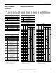
Rockwell Automation Publication 750-IN001N-EN-P - April 2014 3 3 4 4 5 5 18.5 kW 22 kW 30 kW 37 kW 45 kW 55 kW 7 7 7 132 kW 160 kW 200 kW 250 kW Catalog Number 20x…C011 12.7 140 20x…C140 154.0 456 20x…C456 501.6 20x…C367 403.7 20x…C302 332.2 302 367 20x…C260 286.0 20x…C205 225.5 20x…C170 187.0 260 205 170 20x…C104 114.4 20x…C085 93.5 85 104 20x…C072 79.2 20x…C060 66.0 20x…C043 47.3 20x…C037 40.7 72 60 43 37 20x…C030 33.0 20x…C022 24.
(1) “Applied Rating” refers to the motor that will be connected to the drive. For example, a “C022” drive can be used in Normal Duty mode on a 11 kW motor, or in Heavy Duty mode on a 7.5 kW motor. A “C015” drive can be used in Heavy Duty mode on a 5.5 kW motor with the same ratings as a “C011.” The drive can be programmed for either mode. Wiring and fuses can be sized based on the programmed mode.
Rockwell Automation Publication 750-IN001N-EN-P - April 2014 8 8 8 9 9 9 9 355 kW 400 kW 450 kW 400 kW 500 kW 560 kW 630 kW Heavy 472 Light Normal Heavy 1090 1090 Heavy 1040 1090 Normal 1040 910 Light Heavy Normal 910 1040 Heavy Heavy 880 750 Light Light 796 832 Normal 20G…C1K4 20G…C1K1 20G…C1K0 20G…C1K2 20G…C1K0 20G…C910 20G…C910 20G…C1K1 20G…C1K0 20G…C910 20G…C770 20G…C750 20G…C770 20G…C750 Normal 750 770 20G…C770 20G…C650 Heavy 642 20G…C
9 Applied Rating (1) 710 kW Heavy 1175 10 10 1250 kW 1400 kW 2330 Light Normal Heavy 1800 2150 Light 1715 Normal Light 20G…C2K1 20G…C2K1 20G…C2K1 20G…C1K6 20G…C1K6 20G…C1K5 20G…C1K5 20G…C1K4 20G…C1K4 20G…C1K2 20G…C1K6 20G…C1K5 20G…C1K2 20G…C1K1 Catalog Number 2563 2365 2700 1887 1749 1760 1628 1628 1612 1612 1988 1763 1293 1293 1 min 2796 3240 3240 2058 2385 – 2220 – 2198 – 2385 2220 1872 – 3 sec 2294 2117 1773 1689 1566 1576 1457 1457
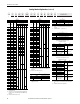
Rockwell Automation Publication 750-IN001N-EN-P - April 2014 7 7 7 200 Hp 250 Hp 300 Hp 350 Hp Catalog Number 415 20x…D415 456.5 20x…D361 397.1 20x…D302 332.2 302 361 20x…D248 272.8 20x…D186 204.6 20x…D156 171.6 20x…D125 137.5 20x…D096 105.6 248 186 156 125 96 20x…D065 71.5 20x…D077 84.7 65 20x…D052 57.2 20x…D040 44.0 20x…D034 37.4 77 52 40 34 20x…D027 29.7 20x…D022 24.2 22 27 20x…D014 15.4 20x…D011 16.5 20x…D8P0 12.0 20x…D5P0 7.5 20x…D3P4 5.1 20x…D2P1 3.
(1) “Applied Rating” refers to the motor that will be connected to the drive. For example, a “D022” drive can be used in Normal Duty mode on a 15 Hp motor, or in Heavy Duty mode on a 10 Hp motor. A “D014” drive can be used in Heavy Duty mode on a 7.5 Hp motor with the same ratings as a “D011.” The drive can be programmed for either mode. Wiring and fuses can be sized based on the programmed mode.
Rockwell Automation Publication 750-IN001N-EN-P - April 2014 9 900 Hp Normal Heavy 1045 1045 Heavy 960 Light Normal 960 1045 Light Heavy 960 800 Normal 800 Heavy Heavy 710 795 Light Normal 740 800 Light 765 Normal 710 Heavy Light 617 710 Normal 617 Heavy 545 Light Normal 590 Light 545 Heavy 485 545 Light Normal 485 Heavy 454 485 Heavy 414 Heavy Normal 370 430 Duty Cont.
9 1350 Hp 10 1730 10 2070 10 2240 1650 Hp 1750 Hp 2000 Hp Light Normal Heavy Light 20G…D2K0 20G…D2K0 20G…D2K0 20G…D1K5 20G…D1K5 20G…D1K4 20G…D1K4 20G…D1K3 20G…D1K5 20G…D1K3 20G…D1K2 20G…D1K4 20G…D1K2 20G…D1K0 Catalog Number 2464 2277 2595 1821 1678 1694 1562 1562 1905 1502 1502 1703 1249 1249 1 min 2688 3114 3114 1986 2288 – 2130 – 2288 2048 – 2130 1728 – 3 sec 2114 1953 1633 1562 1439 1453 1340 1340 1199 1288 1288 1071 1071 1071 Amps 1
Output Overload Amps Catalog Number Output Overload Amps Drive Sized For Heavy Duty 3 22 20 Hp 20x…E022 24.2 20x…E017 18.7 20x…E011 12.1 33.0 25.5 20x…E022 25.5 16.5 20x…E017 16.5 Rockwell Automation Publication 750-IN001N-EN-P - April 2014 18.0 20x…E018 18.0 6 12 6 18 6 23 10 Hp 15 Hp 20 Hp 6 42 6 53(4), 52(5) 40 Hp 50 Hp continued on page 163 20x…E042 46.2 20x…E053 58.3 6 33 30 Hp 20x…E033 36.3 6 28 20x…E028 30.8 36.0 20x…E024 26.4 79.5 20x…E063 78.0 63.
Output Overload Amps Catalog Number Output Overload Amps 150 Hp 7 242 7 289 250 Hp 300 Hp 340 271.3 20x…E289 317.9 433.5 285 225 170 20x…E242 266.2 363.0 20x…E289 363.0 435.6 227.2 20x…E192 211.2 288.0 20x…E242 288.0 363.0 180.3 20x…E192 216.0 288.0 135.2 145 170 135.2 20x…E144 158.4 216.0 20x…E125 137.5 187.5 20x…E144 187.5 225.0 117.
Rockwell Automation Publication 750-IN001N-EN-P - April 2014 8 8 8 9 9 9 9 9 450 Hp 500 Hp 550 Hp 500 Hp 600 Hp 700 Hp 750 Hp 800 Hp Normal Light 595 Heavy Normal Light 760 760 760 Heavy Normal 700 Heavy 630 Normal 630 Heavy 595 Heavy 595 510 Light 510 545 Normal 460 Normal Heavy 435 425 Light Light 435 Light Heavy 395 510 Normal 395 460 Light 395 Heavy Heavy 329 Normal 355 355 Light 355 Normal 295 Heavy Heavy 272 295 Duty Cont.
Normal Light 10 1430 10 1530 1400 Hp 1500 Hp 20G…E900 20G…E1K4 20G…E1K4 20G…E1K4 20G…E1K1 20G…E1K1 20G…E980 20G…E1K1 1683 1573 1785 1342 1221 1150 1380 1078 1078 990 990 919 908 1223 1 min 1836 2145 2145 1464 1665 – 1665 – 1470 – 1368 – 1260 1470 3 sec 1444 1350 1123 1151 1048 986 868 925 925 849 849 788 779 769 Amps 900 900 900 900 900 900 900 900 900 900 900 900 900 900 Amps 1000 1000 1000 1000 1000 1000 1000 1000 1000 1000
6 6 6 7 90 kW 110 kW 132 kW 263 212 171 20x…F263 20x…F212 20x…F171 20x…F142 20x…F098 20x…F119 119 20x…F082 20x…F061 20x…F050 20x…F046 20x…F034 20x…F030 98 82 61 50 46 34 30 289.3 233.2 188.1 156.2 130.9 107.8 90.2 67.1 55.0 50.6 37.4 33.0 25.3 22.0 16.5 13.2 394.5 318.0 256.5 213.0 178.5 147.0 123.0 91.5 75.0 69.0 51.0 45.0 34.5 30.0 22.5 18.
Rockwell Automation Publication 750-IN001N-EN-P - April 2014 8 8 8 8 9 9 9 9 9 9 400 kW 450 kW 500 kW 530 kW 450 kW 500 kW 560 kW 630 kW 710 kW 750 kW Normal Light Normal 710 765 Light 650 Normal Normal 650 710 Heavy 650 Heavy Normal 590 750 Heavy Heavy Heavy 590 500 460 Light 500 530 Light 500 Normal 460 Heavy 413 Light Normal 415 460 Light 410 Heavy Heavy 370 375 Light Normal 370 Normal Light 370 330 330 Heavy Heavy 265 308 Normal
Normal Light 10 1400 10 1485 1400 kW 1500 kW 20G…F1K4 20G…F1K4 20G…F1K4 20G…F1K0 20G…F1K0 20G…F795 20G…F1K0 20G…F795 20G…F960 20G…F765 20G…F710 20G…F795 20G…F960 Catalog Number 1634 1540 1740 1265 1144 1122 1298 1056 1056 946 869 875 1193 1 min 1782 2100 2100 1380 1560 – 1560 – 1440 – – 1350 1440 3 sec 1399 1319 1093 1083 980 904 815 904 904 810 744 749 749 Amps Amps 900 900 900 900 900 900 900 900 900 900 900 900 900 1000 100
PowerFlex 750-Series AC Drives Motor Overload Protection Electronic Motor Overload Protection: Class 10 motor overload protection according to NEC article 430 and motor over-temperature protection according to NEC article 430.126 (A)(2). UL 508C File E59272. Short Circuit Current Rating Maximum Short Circuit Rating: 200,000 Amps RMS symmetrical (20F & 20G drives only) Actual Short Circuit Rating: Determined by AIC rating of installed fuse/circuit breaker.
PowerFlex 750-Series AC Drives Short Circuit Current Ratings - Floor Mount Drives with Cabinet Options Default ratings (no added protection) shown. A“•” indicates ratings that can be achieved with additional protection.
PowerFlex 750-Series AC Drives Drive Catalog Number Duty Cycle kW Short Circuit Current Rating (kA) Circuit Breaker with Input Contactor Circuit Breaker (P3 with P11) (1) Only (P3) (1) Molded Case Switch Only (P5) (2) Molded Case Switch with Input Contactor (P5 with P11) (2) 400 Volt AC Input continued on page 171 LD 21G…C910 ND HD 21G…C1K0 LD ND HD 21G…C1K1 LD ND HD 21G…C1K2 LD ND HD 21G…C1K4 LD ND HD 21G…C1K5 LD ND HD 560 500 400 630 560 500 710 630 500 800 710 560 850 800 630 900 850 710 100 100
PowerFlex 750-Series AC Drives Drive Catalog Number Duty Cycle Hp Short Circuit Current Rating (kA) Circuit Breaker Circuit Breaker with Input Contactor Only (P3) (1) (P3 with P11) (1) 21G…D430 LD 400 100 30 or • 65 w/600 A Class J fuse 65 ND 350 100 65 HD 300 100 LD 450 100 30 or • 65 w/550…600 A Class J fuse 5 or • 100 w/450…600 A Class J fuse • 18 w/600…800 A Class L fuse • 18 w/500 A CB 30 ND 400 100 30 or • 65 w/600 A Class J fuse 65 HD 350 100 65 LD 500 100 5 or • 100
PowerFlex 750-Series AC Drives Drive Catalog Number Duty Cycle Hp Short Circuit Current Rating (kA) Circuit Breaker Circuit Breaker with Input Contactor Only (P3) (1) (P3 with P11) (1) 21G…D800 LD ND HD LD ND HD LD ND HD LD ND HD LD ND HD LD ND HD 800 700 600 900 800 700 1000 900 750 1100 1000 800 1250 1100 900 1350 1250 1000 100 100 100 100 100 100 100 100 100 100 100 100 100 100 100 100 100 100 Molded Case Switch Only (P5) (2) Molded Case Switch with Input Contactor (P5 with P11) (2) 480 Volt A
PowerFlex 750-Series AC Drives Drive Catalog Number Duty Cycle Hp Short Circuit Current Rating (kA) Circuit Breaker Circuit Breaker with Input Contactor Only (P3) (1) (P3 with P11) (1) 21G…E295 LD 350 50 ND 300 50 HD 250 50 LD 400 50 ND 350 50 HD 300 50 LD 450 50 ND 400 50 HD 350 50 LD 500 50 ND 450 50 HD 350 50 LD 500 35 ND 500 50 HD 400 50 LD 550 35 ND 500 35 HD 450 50 LD ND HD LD ND HD LD ND HD 700 600 500 800 700 600 900 800 700 50 50 50 50 5
PowerFlex 750-Series AC Drives Drive Catalog Number Duty Cycle Hp Short Circuit Current Rating (kA) Circuit Breaker with Input Contactor Circuit Breaker (P3 with P11) (1) Only (P3) (1) 21G…E825 LD ND HD LD ND HD LD ND HD 950 900 750 1000 950 800 1100 1000 900 50 50 50 65 50 50 65 65 50 Molded Case Switch Only (P5) (2) Molded Case Switch with Input Contactor (P5 with P11) (2) – – – – – – – – – – – – – – – – – – 600 Volt AC Input 21G…E900 21G…E980 – – – – – – – – – (1) These circuit breakers
PowerFlex 750-Series AC Drives Input Contactor Precautions ATTENTION: A contactor or other device that routinely disconnects and reapplies the AC line to the drive to start and stop the motor can cause drive hardware damage. The drive is designed to use control input signals that will start and stop the motor. If an input device is used, operation must not exceed one cycle per minute or drive damage will occur. ATTENTION: The drive start/stop/enable control circuitry includes solid state components.
PowerFlex 750-Series AC Drives Power Disconnects – Drives with Cabinet Options Option Code Applicable Description Frame P3 8…10 This option is for disconnecting drive power. All breakers include flange style handle operators that are door interlocking and padlockable. Input Thermal Magnetic Circuit Breaker Input Non-Fused P5 Molded Case Disconnect Switch 8 Only This option is for disconnecting drive power. All switches include flange style handle operators that are door interlocking and padlockable.
PowerFlex 750-Series AC Drives Transformer Panel – Drives with Cabinet Options Option Code Applicable Frame – 8 (IP54 enclosures only.) 9 (All enclosures.) Fuses Thermostat – 8…9 Description 690 VAC, 6A, IEC gl-gG FU9,FU10 (690VAC) 600 VAC, 6A, Class CC FU9,FU10 (400,480,600VAC) 600 VAC, 5A, Class CC FU11 600 VAC, 6A, Class CC FU12 (120VAC) 600 VAC, 3A, Class CC FU12 (230VAC) FU13 (Frame 8 with P11 or P12 Only) 600 VAC, 5A, Class CC Thermostat is used in all option bays and enclosure types.
PowerFlex 750-Series AC Drives Input Power Circuit Breakers and Disconnect Switches Refer to page 12 for an explanation of where to locate drive ratings on the nameplate.
PowerFlex 750-Series AC Drives Table 17 - 480V, 60 Hz Input - Code P3 Thermal Magnetic Circuit Breaker Options Hp Amps Duty 300 350 370 430 414 454 485 485 485 545 545 545 590 617 617 710 710 765 740 800 Heavy Normal Heavy Heavy Light Normal Heavy Light Normal Heavy Light Normal Heavy Light Normal Light Normal Light 400 450 500 600 650 700 Line Side Terminal Lugs 140U-L-TL6A2 140U-L-TL6A2 140U-L-TL6A2 140U-L-TL6A2 140U-N-TLA3A 140U-N-TLA3A 140U-N-TLA3A 140U-N-TLA3A 140U-N-TLA3A 140U-N-TLA3A 140U-
PowerFlex 750-Series AC Drives Table 19 - 600V, 50 Hz Input - Code P3 Thermal Magnetic Circuit Breaker Options Hp Amps Duty 250 300 272 295 295 329 355 355 355 395 395 395 425 435 435 460 460 510 510 545 Heavy Heavy Normal Heavy Heavy Light Normal Heavy Light Normal Heavy Light Normal Light Normal Light Normal Light 350 400 450 500 550 Line Side Terminal Lugs 140U-L-TL6A2 140U-L-TL6A2 140U-L-TL6A2 140U-L-TL6A2 140U-L-TL6A2 140U-L-TL6A2 140U-L-TL6A2 140U-L-TL6A2 140U-L-TL6A2 140U-L-TL6A2 140U-L-T
PowerFlex 750-Series AC Drives Table 21 - 690V, 60 Hz Input - Code P3 Thermal Magnetic Circuit Breaker Options kW Amps Duty 200 250 215 265 265 308 330 330 370 370 370 375 410 413 415 460 460 500 500 530 Heavy Heavy Normal Heavy Light Normal Heavy Light Normal Heavy Light Heavy Normal Light Normal Light Normal Light 300 315 355 375 400 450 500 530 Line Side Terminal Lugs 140U-L-TL6A2 140U-L-TL6A2 140U-L-TL6A2 140U-L-TL6A2 140U-L-TL6A2 140U-L-TL6A2 140U-L-TL6A2 140U-L-TL6A2 140U-L-TL6A2 140U-L-TL6A
PowerFlex 750-Series AC Drives Cabinet Options Bay Accessories Figure 93 - Accessory Overview ➊ ➋ ➌ ➍ ➎ ➏ Floor Mount Frame 8 No.
PowerFlex 750-Series AC Drives Figure 94 - Option P3 or P5 Disconnect ➊ ➊ P3 or P5 ➋ Drive Motor U / T1 V / T2 W / T3 ➌ Floor Mount Frame 8 No. ➊ ➋ ➌ 184 Floor Mount Frame 9 Name R/L1, S/L2, T/L3 PE U/T1, V/T2, W/T3 Description Three-phase input power connection. Three-phase input ground. Motor connection made at drive power bus. See page 141.
PowerFlex 750-Series AC Drives Figure 95 - Option P3 or P5 Disconnect and Option P11 Input Contactor (Floor Mount Frame 8 Only) ➊ P3 or P5 ➋ P11 Drive Motor U / T1 V / T2 W / T3 ➌ No. ➊ ➋ ➌ Name R/L1, S/L2, T/L3 PE U/T1, V/T2, W/T3 Description Three-phase input power connection. Three-phase input ground. Motor connection made at drive power bus. See page 141.
PowerFlex 750-Series AC Drives Figure 96 - Option P3 or P5 Disconnect, Option P11 Input Contactor, and Option L1 or L3 Input Reactor (Floor Mount Frame 8 Only) ➊ P3 or P5 ➋ P11 L1 or L3 Drive Motor U / T1 V / T2 W / T3 ➌ No. ➊ ➋ ➌ 186 Name R/L1, S/L2, T/L3 PE U/T1, V/T2, W/T3 Description Three-phase input power connection. Three-phase input ground. Motor connection made at drive power bus. See page 141.
PowerFlex 750-Series AC Drives Figure 97 - Option P3 or P5 Disconnect, Option P11 Input Contactor, and Option L2 or L4 Output Reactor (Floor Mount Frame 8 Only) ➊ P3 or P5 P11 ➋ Drive L2 or L4 Output Terminal Motor ø15 (0.6) 4 Places 44.5 (1.75) 21.5 (0.85) 70.5 (2.80) ➌ 19.1 (0.75) ➍ No. ➊ ➋ ➌ ➍ Name R/L1, S/L2, T/L3 PE PE U/T1, V/T2, W/T3 Description Three-phase input power connection. Three-phase input ground. Three-phase motor ground. Motor connection.
PowerFlex 750-Series AC Drives Figure 98 - Option P3 or P5 Disconnect, Option P12 Output Contactor, and Option L2 or L4 Output Reactor (Floor Mount Frame 8 Only) ➊ P3 or P5 ➋ Drive P12 L2 or L4 Output Terminal Motor ø15 (0.6) 4 Places 44.5 (1.75) 21.5 (0.85) ➌ 70.5 (2.80) ➍ No. ➊ ➋ ➌ ➍ 188 Name R/L1, S/L2, T/L3 PE PE U/T1, V/T2, W/T3 Description Three-phase input power connection. Three-phase input ground. Three-phase motor ground. Motor connection.
PowerFlex 750-Series AC Drives Figure 99 - Option P3 or P5 Disconnect and Option L1 or L3 Input Reactor ➊ P3 or P5 ➋ ➊ L1 or L3 Drive Motor U / T1 V / T2 W / T3 ➌ Floor Mount Frame 8 No. ➊ ➋ ➋ Floor Mount Frame 9 Name R/L1, S/L2, T/L3 PE U/T1, V/T2, W/T3 Description Three-phase input power connection. Three-phase input ground. Motor connection made at drive power bus. See page 141.
PowerFlex 750-Series AC Drives Figure 100 - Option P3 or P5 Disconnect and Option L2 or L4 Output Reactor ➊ P3 or P5 ➋ ➊ Drive L2 or L4 Output Terminal Motor ➌ ➍ U / T1 V / T2 W / T3 ø15 (0.6) 4 Places 44.5 (1.75) 21.5 (0.85) 70.5 (2.80) 19.1 (0.75) ➍ Floor Mount Frame 8 No. ➊ ➋ ➌ ➍ 190 Floor Mount Frame 9 Name R/L1, S/L2, T/L3 PE PE U/T1, V/T2, W/T3 Description Three-phase input power connection. Three-phase input ground. Three-phase motor ground. Motor connection.
PowerFlex 750-Series AC Drives Figure 101 - Option P3 or P5 Disconnect and Option P12 Output Contactor (Floor Mount Frame 8 Only) ➊ P3 or P5 ➋ Drive P12 Motor ➍ ➌ No. ➊ ➋ ➌ ➍ Name R/L1, S/L2, T/L3 PE PE U/T1, V/T2, W/T3 Description Three-phase input power connection. Three-phase input ground. Three-phase motor ground. Motor connection.
PowerFlex 750-Series AC Drives Table 23 - 400V, 50 Hz Input - Code P12 Output Contactor Options (Floor Mount Frame 8 Only) kW 200 250 315 315 355 400 450 Amps 385 460 456 472 540 540 540 585 567 585 612 650 642 750 750 770 796 832 Duty Heavy Normal Heavy Heavy Light Normal Heavy Light Normal Heavy Light Normal Heavy Light Normal Normal Light Light Contactor Cat. No.
PowerFlex 750-Series AC Drives Table 25 - 600V, 50 Hz Input - Code P12 Output Contactor Options (Floor Mount Frame 8 Only) Hp 250 300 350 400 450 500 550 Amps 272 295 295 329 355 355 355 395 395 395 425 435 435 460 460 510 510 545 Duty Heavy Heavy Normal Heavy Heavy Light Normal Heavy Light Normal Heavy Light Normal Light Normal Light Normal Light Contactor Cat. No.
PowerFlex 750-Series AC Drives Drive Power Jumper Configuration PowerFlex 750-Series drives contain protective MOVs and common mode capacitors that are referenced to ground. To guard against drive damage and/or operation problems, these devices must be properly configured according to Table 29.
PowerFlex 750-Series AC Drives Wall Mount Frames 1…7 PowerFlex 750-Series drives, Frames 1…7, leave the factory with Jumpers PE-A and PE-B in one of two possible configurations. Reconfigure these jumpers based on the power source type available. IMPORTANT Table 27 - Power Jumper Default Configurations Cat. No.
PowerFlex 750-Series AC Drives Table 30 - Recommended Power Jumper Configurations Floor Mount Frames 8…10 Power Source Type Jumper PE-A1 (1) (MOV) Disconnected Non-Solid Ground • AC fed ungrounded • Impedance grounded • B phase ground • DC fed from an active converter Solid Ground Connected • AC fed solidly grounded • DC fed from passive rectifier which has a solidly grounded AC source Jumper PE-A2 (Input Filter Caps) Disconnected Jumper PE-B (DC Bus Common mode Caps) Disconnected Connected Connected
PowerFlex 750-Series AC Drives Wall Mount Frames 2…5 Power Jumper Screw Removal and Storage Wall/Flange Mount Frames 2…5 use jumper screws to complete an electrical connection when installed. Install or remove jumper screws according to the recommendations in Table 29. ATTENTION: Hazard of equipment damage exists if jumpers are not properly disconnected. For Frames 2…5, completely remove the jumper screw from the circuit board.
PowerFlex 750-Series AC Drives Wall Mount Frames 1, 6, and 7 Power Jumper Wire Removal and Storage Wall/Flange Mount Frames 1, 6, and 7 use jumper wires to complete an electrical connection when installed. Install or remove jumper wires according to the recommendations in Table 29. ATTENTION: Hazard of equipment damage exists if jumpers are not properly disconnected. For Frames 1, 6, and 7, secure the disconnected jumper wire to the insulated position provided.
PowerFlex 750-Series AC Drives Figure 108 - Wall Mount Frame 6 Jumper Wire Locations Disconnected Connected Common Mode PE-B PE-B E4 E4 MOV When jumper wires are connected: • Recommended torque (screws and nuts) = 1.36 N•m (12.
PowerFlex 750-Series AC Drives Figure 109 - Wall Mount Frame 7 Jumper Wire Locations Disconnected Connected Common Mode MOV When jumper wires are connected: • Recommended torque (screws and nuts) = 1.36 N•m (12.
PowerFlex 750-Series AC Drives Floor Mount Frames 8…10 Drive Assembly Jumper Removal and Storage Frame 8…10 drive assemblies use jumper plugs to complete an electrical connection when installed. Install or remove jumper plugs according to the recommendations in Table 30. ATTENTION: Hazard of equipment damage exists if jumpers are not properly disconnected or are set differently between drive assemblies.
PowerFlex 750-Series AC Drives Figure 111 - Drive Assembly PE-A1 MOV and PE-A2 Input Filter Caps Jumper Location Connected Disconnected Connected Disconnected PE-A1 and GND positions on early production drives. When the PE-A1 jumper wire is connected: • Recommended torque = 1.8 N•m (16.0 lb•in) • Recommended screwdriver = T20 Hexalobular IMPORTANT 202 PE-A1 and PE-A2 jumper are only used by three-phase input drive assemblies and are not applicable to Common DC Input drives assemblies.
PowerFlex 750-Series AC Drives Step 5: I/O Wiring Important points to remember about I/O wiring: • Always use copper wire. • Wire with an insulation rating of 600V or greater is recommended. • Control and signal wires should be separated from power wires by at least 0.3 meters (1 foot). • For CE compliance, 115 volt digital input wiring must be shielded or must not exceed 30 meters (98 feet) in length.
PowerFlex 750-Series AC Drives I/O Terminal Blocks Table 31 - Main Control Board I/O Terminal Block Specifications Name 753 Control Module TB1, TB2, and TB3 755 Control Module TB1 Wire Size Range Maximum Minimum 2.5 mm2 0.3 mm2 (14 AWG) (28 AWG) 0.3 mm2 2.5 mm2 (14 AWG) (28 AWG) Torque Maximum 0.25 N•m (2.2 lb•in) 0.25 N•m (2.2 lb•in) Recommended 0.2 N•m (1.8 lb•in) 0.2 N•m (1.8 lb•in) Strip Length 6 mm (0.24 in.) 6 mm (0.24 in.
PowerFlex 750-Series AC Drives Table 35 - I/O Wire Recommendations Type Signal (1) (2)(3) Wire Type(s) Description Standard Analog I/O – Remote Pot – Encoder/ Pulse I/O <30 m (100 ft) Combined 0.750 mm2 (18AWG), twisted pair, 100% shield with drain. 300V, 75…90 °C 0.750 mm2 (18AWG), 3 conductor, shielded. (167…194 °F) 0.196 mm2 (24AWG) individually shielded pairs. Encoder/ Pulse I/O 30 to 152 m (100 to 500 ft) Signal 0.196 mm2 (24AWG) individually shielded pairs. Power 0.750 mm2 (18AWG) in.
PowerFlex 750-Series AC Drives Access Drive Control Pod 1. Remove drive cover Wall Mount Frames 1…5 – Squeeze locking tabs and pull out bottom of cover. – Pull cover down and away from the chassis. Wall Mount Frames 6…7 – Loosen door screws. – Gently pry the door open to remove.
PowerFlex 750-Series AC Drives Floor Mount Frames 8…10 – Remove top screws. – Loosen bottom screws. – Remove the right front cover.
PowerFlex 750-Series AC Drives 2. Frame 1 – Lift the chassis cover. Frames 2…7 – Lift the Human Interface Module (HIM) cradle. Wall Mount Frame 1 – Loosen the retention screw. – Use a screwdriver to release the chassis cover locking tabs. – Lift the chassis cover until the latch engages.
PowerFlex 750-Series AC Drives Wall Mount Frames 2…7 – Loosen the retention screw. – Lift the cradle until the latch engages. Floor Mount Frames 8…10 – Loosen the retention screw. – Lift the cradle until the latch engages.
PowerFlex 750-Series AC Drives PowerFlex 753 Main Control Board ➊ ➋ ➌ ➍ ➎ ➏ ➐ ➑ ➒ ➓ Table 36 - 753 Main Control Board Details No. ➊ ➋ ➌ Name HIM Connector Fan Connector Battery Receptacle ➍ ENABLE Jumper ➎ ➏ ➐ ➑ ➒ ➓ SAFETY Jumper Jumper J4 Input Mode TB1 DPI Port 2 TB3 TB2 Description DPI Port 1 (HIM Cradle) connection. Power supply for internal cooling fan (Frames 2 & 3). User installed CR1220 lithium coin cell battery provides power to the Real Time Clock (Optional, not supplied).
PowerFlex 750-Series AC Drives Table 38 - TB1 Terminal Designations Ao0Ao0+ 10VC +10V Ai0Ai0+ PtcPtc+ To0 24VC +24V Di C Di 1 Di 2 Terminal Name Description Ao0– Ao0+ Analog Out 0 (–) Analog Out 0 (+) 10VC +10V Ai0– Ai0+ 10 Volt Common +10 Volt Reference Analog Input 0 (–) Analog Input 0 (+) Bipolar, ±10V (1), 11 bit & sign, 2 k ohm minimum load. 4-20 mA (1), 11 bit & sign, 400 ohm maximum load. For (+) 10 Volt references. 2k ohm minimum.
PowerFlex 750-Series AC Drives PowerFlex 755 Main Control Board Wall Mount Frames 1…7 ➊ ➋ ➌ ➍ ➎ ➏ ➐ ➑ ➒ Table 41 - Control Board Details No. ➊ ➋ ➌ Name HIM Connector Fan Connector Battery Receptacle ➍ ➎ DPI Port 2 Embedded EtherNet/IP(1) Address Selectors ➏ ➐ ➑ Embedded EtherNet/IP(1) Connector SAFETY Jumper ENABLE Jumper ➒ TB1 Description DPI Port 1 (HIM Cradle) connection. Power supply for internal cooling fan (Frames 2 & 3).
PowerFlex 750-Series AC Drives Floor Mount Frames 8…10 ➊ ➋ ➌ ➍ ➎ ➏ ➐ ➑ Table 43 - Control Board Details No. Name ➊ HIM Connector ➋ Fan Connector ➌ Battery Receptacle ➍ ➎ DPI Port 2 ENABLE Jumper ➏ Embedded EtherNet/IP(1) Address Selectors ➐ ➑ Embedded EtherNet/IP(1) Connector TB1 Description DPI Port 1 (HIM Cradle) connection. Power supply for internal cooling fan. User installed CR1220 lithium coin cell battery provides power to the Real Time Clock (Optional, not supplied).
PowerFlex 750-Series AC Drives Hardware Enable Circuitry Each main control board has one digital input, Digital Input 0, that can be used as a general purpose programmable input, or by removal of a jumper, configured as a dedicated hardware enable, which is unaffected by parameter settings. • PowerFlex 753 - Digital Input 0 is found on TB3 • PowerFlex 755 - Digital Input 0 is found on TB1 To configure Digital Input 0 as a dedicated hardware enable, complete the following steps. 1.
PowerFlex 750-Series AC Drives PowerFlex 755 - ENABLE Jumper Location (Floor Mount Frames 8…10) Rockwell Automation Publication 750-IN001N-EN-P - April 2014 215
PowerFlex 750-Series AC Drives Safety Enable Circuitry The drive ships with the safety enable jumper (SAFETY) installed. This jumper must be removed when using the safe torque off or speed monitoring safety options. IMPORTANT Failure to remove the jumper when using either safety option will cause the drive to fault when a start command is issued.
PowerFlex 750-Series AC Drives PowerFlex 755 Fiber Optic Interface Board Floor Mount Frames 8…10 ➊ ➋ ➌ P1 P2 P3 ➍ Table 45 - Fiber Interface Board Details No. Name ➊ Main Control Board Connector ➋ P13 ➌ P14 ➍ Inverter Connections Description 98 pin main control board interface connection. Connections for user-supplied 24 volt power. Powers control circuits when main power is removed. Connections for internal drive-supplied 24 volt power.
PowerFlex 750-Series AC Drives AC Input Drive Control and Power Terminal Block Floor Mount Frames 8…10 AC Input Drive Control Panel Table 48 - TB2 Terminal Designations Fixed I/O 1 2 3 4 Terminal Name Description Rating 1 Output Relay common 125V AC, 10 A max., 1250 VA Resistive Only 2 3 4 SHUNT TRIP COMMON SHUNT TRIP NO FAN 240VAC OUT NEUTRAL FAN 240VAC OUT HOT Output Relay normally open contact. Connections for cooling fans. Related Param 16 on Port 11 240V AC, 50/60 Hz, 1.
PowerFlex 750-Series AC Drives Common DC Input Drive Control and Power Terminal Blocks Floor Mount Frames 8…10 TB5 - See Table 52 TB4 - See Table 51 TB3 - See Table 50 TB2 - See Table 49 Common DC Input Drive Control Panel Table 49 - TB2 Terminal Designations Fixed I/O 1 2 3 4 5 6 Terminal Name 1 UPS 120VAC IN NEUTRAL 2 UPS 120VAC IN HOT 3 4 5 6 Description Rating N/A Connections for Uninterruptible Power Supply (UPS).(1) CONTROL 120/240VAC IN NEUTRAL Connections for control power N/A supply.
PowerFlex 750-Series AC Drives DC Precharge Board The DC precharge board provides sensing of bus voltage, monitoring of bus fuses and control over all precharge hardware. Table 50 - TB3 Terminal Designations Fixed I/O Terminal 1 2 3 1 4 2 5 3 4 6 5 6 7 7 8 8 9 9 10 11 10 12 13 11 12 13 Factory Jumper Settings: • TB3-1 and TB3-3 • TB3-1 and TB3-5 • TB3-2 and TB3-4 • TB3-2 and TB3-6 Name Description I/O 24V Drive supplied 24V DC I/O power. I/O 24V COMMON External precharge close/open input. EXT.
PowerFlex 750-Series AC Drives 120V Output Wiring for Drive Control The Common DC Input drive provides limited 120V control power for use with the drive control pod option modules. For terminal block wiring specifications see Table 34 - on page 204.
PowerFlex 750-Series AC Drives Control Transformer Connections - Common DC Input Drives The Common DC Input drive control transformer is factory set to 120V AC input. A 240V AC input setting is also available by changing primary wire connections. Figure 112 - Control Transformer Voltage Settings - Floor Mount Frames 8…10 P2 1.
PowerFlex 750-Series AC Drives Uninterruptible Power Supply Connections - Common DC Input Drives The user-supplied 120V AC UPS is connected to the lower 120V rail in the back of the Common DC Input drive cabinet. The UPS rail is only installed when the P30 UPS Control Bus option is selected. The rail is connected to TB2-1 and TB2-2 on the Common DC Input drive control panel. To use 120V AC UPS power, configure the TB5 jumpers as shown in Table 53 - on page 221.
PowerFlex 750-Series AC Drives 120/240V AC Power Supply Connections - Common DC Input Drives The drive-supplied 120/240V AC is wired through a circuit breaker mounted in the Common DC Input drive cabinet. The circuit breaker is connected to TB2-3 and TB2-4 on the Common DC Input drive control panel. ATTENTION: To avoid an electric shock hazard when servicing the drive, a means for Lockout/Tagout of an external 120/240V power source must be provided. Or the circuit breaker SW5 must be locked and tagged.
PowerFlex 750-Series AC Drives 753 Main Control Board I/O Wiring Examples 753 Main Control Board TB1 Wiring Examples Input/Output Potentiometer Unipolar Speed Reference 10k Ohm Pot.
PowerFlex 750-Series AC Drives 753 Main Control Board TB1 Wiring Examples (Continued) Input/Output Analog Current Input Unipolar Speed Reference 0-20 mA Input Connection Example Common + Ai0– Ai0+ 753 Main Control Board TB1 J4 HW Input PTC Standard = No design standard PTC Nominal = 1.8 k Ohm PTC Trip = 3.1 k Ohm PTC Reset = 2.
PowerFlex 750-Series AC Drives 753 Main Control Board TB1 Wiring Examples (Continued) Input/Output 3-Wire Control Internal supply Connection Example Required Parameter Changes • Set Selection Port 0: P158 [DI Stop] = Port 0: P220 [Digital In Sts], bit 1 = Digital In 1 Port 0: P161 [DI Start] = Port 0: P220 [Digital In Sts], bit 2 = Digital In 2 • View Results Port 0: P220 [Digital In Sts] Port 0: P935 [Drive Status 1] 24VC +24V Di C Di 1 Di 2 Stop Start 753 Main Control Board TB1 3-Wire Control Extern
PowerFlex 750-Series AC Drives Drive Device Ports Connectors, embedded devices, and installed option modules such as I/O, communication adapters, and DeviceLogix, have unique port number assignments. Connectors and embedded devices have fixed port numbers that cannot be changed. Option modules are assigned a port number when installed.
PowerFlex 750-Series AC Drives Option Module Installation Compatible port locations may be restricted for each module. An icon with position number(s) is provided to indicate which option module ports are compatible. For example, the icon to the right indicates that the option module is only compatible with port 4. ATTENTION: Hazard of equipment damage exists if an option module is installed or removed while the drive is powered.
PowerFlex 750-Series AC Drives 11-Series I/O Module Table 54 - Analog Input Mode Jumpers 20-750-1132C-2R (24 Volts DC) 20-750-1133C-1R2T (24 Volts DC) 20-750-1132D-2R (120 Volts AC) Voltage Mode P4 1 1 Current Mode P5 P4 2 2 1 1 P5 2 2 Table 55 - TB1 Terminal Designations –10V 10VC +10V Sh Ao0– Ao0+ Sh Ai0– Ai0+ Sh Di0 Di0P Di1 Di1P Di2 Di2P Ip Ic EnC EnNO Terminal Name Description –10V 10VC +10V Sh –10 Volt Reference 10 Volt Common +10 Volt Reference Shield Ao0– Ao0+ Sh Analog Out 0 (–)
PowerFlex 750-Series AC Drives Table 56 - TB2 Terminal Designations (2 Relay Outputs: 2R) Relay Out R0NO R0C R0NC Terminal Name Description R0NO R0C R0NC Relay 0 N.O. Relay 0 Common Relay 0 N.C. Relay Normally Open contact output: 240V AC, 30V DC, 3.5 A max. General Purpose (Inductive) / Resistive R1NO R1C R1NC Relay 1 N.O. Relay 1 Common Relay 1 N.C. Relay Normally Closed contact output: 240V AC, 30V DC, 5 A max.
PowerFlex 750-Series AC Drives 11-Series I/O Wiring Examples 11-Series I/O Module TB1 Wiring Examples Input/Output Potentiometer Unipolar Speed Reference 10k Ohm Pot.
PowerFlex 750-Series AC Drives 11-Series I/O Module TB1 Wiring Examples (Continued) Input/Output Analog Voltage Input Unipolar Speed Reference 0 to +10V Input Connection Example Common + Ai0– Ai0+ Sh 11-Series I/O Module TB1 P4 1 1 P5 Required Parameter Changes • Set Direction Mode Port 0: P308 [Direction Mode] = 0 “Unipolar” • Set Selection Port 0: P545 [Spd Ref A Sel] = Port X (11-Series I/O Module): P50 [Anlg In0 Value] • Adjust Scaling Port X (11-Series I/O Module): P51 [Anlg In1 Hi] = 10 Volt
PowerFlex 750-Series AC Drives 11-Series I/O Module TB1 Wiring Examples (Continued) Input/Output 2-Wire Control NonReversing 24V DC internal supply Connection Example Stop-Run Di0 Di0P 11-Series I/O Module TB1 P3 3 3 Required Parameter Changes • Set Direction Mode Port 0: P308 [Direction Mode] = 2 “Rev Disable” • Configuration Port 0: P150 [Digital In Cfg] = 1 “Run Level” • Set Selection Port 0: P163 [DI Run] = Port X (11-Series I/O Module): P1 [Dig In Sts], bit 0 = Input 0 • View Results Port X (11-
PowerFlex 750-Series AC Drives 11-Series I/O Module TB1 Wiring Examples (Continued) Input/Output 3-Wire Control External 24 volt supply 20-750-1132C-2R 20-750-1133C-1R2T Connection Example Start Stop Di0 Di0P Di1 Di1P +24V Common Required Parameter Changes • Set Selection Port 0: P158 [DI Stop] = Port X (11-Series I/O Module): P1 [Dig In Sts], bit 0 = Input 0 Port 0: P161 [DI Start] = Port X (11-Series I/O Module): P1 [Dig In Sts], bit 1 = Input 1 • View Results Port X (11-Series I/O Module): P1 [Dig
PowerFlex 750-Series AC Drives 11-Series I/O Module TB1 Wiring Examples (Continued) Input/Output Digital Input PLC Output Module External supply Connection Example Di0 Control from Prog.
PowerFlex 750-Series AC Drives 11-Series I/O Module TB1 Wiring Examples (Continued) Input/Output Digital Output Internal supply 20-750-1133C-1R2T Connection Example 753 755 24VC +24V +24V 24VC Required Parameter Changes • Set Selection Port X (11-Series I/O Module): P20 [TO0 Sel] = Port 0: P935 [Drive Status 1], bit 7 = Faulted • View Results Port X (11-Series I/O Module): P5 [Dig Out Sts] T0 TC T1 Main Control Board TB1 11-Series I/O Module TB2 P3 3 3 P8 1 1 Digital Output External supply 20-75
PowerFlex 750-Series AC Drives 11-Series I/O Relay Wiring Examples Input/Output Relay Output External supply Connection Example 753 Main Control Board R0NC R0C R0NO Required Parameter Changes • Set Selection Port 0: P230 [RO0 Sel] = Port 0: P935 [Drive Status 1], bit 7 = Faulted • View Results Port 0: P225 [Dig Out Sts] Power Source 11-Series I/O Module • Set Selection Port X (11-Series I/O Module): P10 [RO0 Sel] = Port 0: P935 [Drive Status 1], bit 7 = Faulted • View Results Port X (11-Series I/O Mod
PowerFlex 750-Series AC Drives 22-Series I/O Module Table 59 - Input Mode Jumpers 20-750-2262C-2R (24 Volts DC) 20-750-2263C-1R2T (24 Volts DC) 20-750-2262D-2R (120 Volts AC) Jumper Position Voltage Mode Current Mode Ai1 Ai1 Ai0 Ai0 Table 60 - TB1 Terminal Designations Sh Sh PTC– PTC+ Ao0– Ao0+ Ao1– Ao1+ –10V 10VC +10V Ai0– Ai0+ Ai1– Ai1+ 24VC +24V DiC Di0 Di1 Di2 Di3 Di4 Di5 Terminal Name Description Sh Sh Ptc– Ptc+ Ao0– Ao0+ Ao1– Ao1+ –10V 10VC +10V Ai0– Ai0+ Ai1– Ai1+ 24VC +24V Shield Term
PowerFlex 750-Series AC Drives Table 61 - TB2 Terminal Designations (2 Relay Outputs: 2R) Relay Out R0NO R0C R0NC Terminal Name Description R0NO R0C R0NC Relay 0 N.O. Relay 0 Common Relay 0 N.C. Relay Normally Open contact output: 240V AC, 24V DC, 2 A max. General Purpose (Inductive) / Resistive R1NO R1C R1NC Relay 1 N.O. Relay 1 Common Relay 1 N.C. Relay Normally Closed contact output: 240V AC, 24V DC, 2 A max.
PowerFlex 750-Series AC Drives 22-Series I/O Wiring Examples 22-Series I/O Module TB1 Wiring Examples Input/Output Potentiometer Unipolar Speed Reference 10k Ohm Pot.
PowerFlex 750-Series AC Drives 22-Series I/O Module TB1 Wiring Examples (Continued) Input/Output Analog Current Input Unipolar Speed Reference 0-20 mA Input Connection Example Common + Ai0– Ai0+ 22-Series I/O Module TB1 Ai1 Ai0 HW Input PTC Standard = DIN 44082 PTC Nominal = 1.8 k Ohm PTC Trip = 3.1 k Ohm PTC Reset = 2.2 k Ohm Short Circuit Trip = 300 Ohm Ptc– Ptc+ 1.
PowerFlex 750-Series AC Drives 22-Series I/O Module TB1 Wiring Examples (Continued) Input/Output 3-Wire Control Internal supply Connection Example Required Parameter Changes • Set Selection Port 0: P158 [DI Stop] = Port X (22-Series I/O Module): P1 [Dig In Sts], bit 0 = Input 0 Port 0: P161 [DI Start] = Port X (22-Series I/O Module): P1 [Dig In Sts], bit 1 = Input 1 • View Results Port X (22-Series I/O Module): P1 [Dig In Sts] Port 0: P935 [Drive Status 1] 24VC +24V Di C Di 0 Di 1 Stop Start 22-Series
PowerFlex 750-Series AC Drives 22-Series I/O Module TB1 Wiring Examples (Continued) Input/Output Digital Output Internal supply 20-750-2263C-1R2T Connection Example Required Parameter Changes • Set Selection Port X (22-Series I/O Module): P20 [TO0 Sel] = Port 0: P935 [Drive Status 1], bit 7 = Faulted • View Results Port X (22-Series I/O Module): P5 [Dig Out Sts] 24VC +24V T0 TC T1 22-Series I/O Module TB1 22-Series I/O Module TB2 Digital Output External supply 20-750-2263C-1R2T +24V OR T0 TC T1 Com
PowerFlex 750-Series AC Drives Safe Torque Off Option Module The safe torque off option is just one component in a safety control system. Components in the system must be chosen and applied appropriately to achieve the desired level of operational safety. For detailed information on applying this option, refer to the PowerFlex 750-Series Safe Torque Off User Manual, publication 750-UM002.
PowerFlex 750-Series AC Drives Port Assignment • When used in an Integrated Motion application, the Safe Torque Off option must be installed in port 6. • Only one safety option module can be installed at a time. Multiple safety options or duplicate safety option installations are not supported. Jumper Settings • Ensure the hardware enable jumper (ENABLE) on the main control board is installed. Refer to page 214 for location. If not installed, the drive will fault when powered up.
PowerFlex 750-Series AC Drives Safe Speed Monitor Option Module The Safe Speed Monitor option is just one component in a safety control system. Components in the system must be chosen and applied appropriately to achieve the desired level of operational safety. For detailed information on applying this option, refer to the Safe Speed Monitor Option Module for PowerFlex 750Series AC Drives Safety Reference Manual, publication 750-RM001.
PowerFlex 750-Series AC Drives Important Safe Speed Monitor Option Module Installation Notes 20-750-S1 20-750-DENC-1 Cabling • Safety input wiring must be protected against external damage by cable ducting, conduit, armored cable or other means. • Shielded cable is required. • When installed in a Frame 8 or larger drive, an EMC Core Kit, catalog number 20-750-EMCSSM1-F8, is required. Feedback Devices The Safe Speed Monitor option must be used with one of the following feedback devices.
PowerFlex 750-Series AC Drives Auxiliary Power Supply Option Module Table 66 - TB1 Terminal Designations 20-750-APS AP+ AP– Sh AP+ APSh IMPORTANT Terminal Name AP+ +24 Volt Auxiliary Power AP– Auxiliary Power Common Sh Shield Description Connections for customer supplied power supply: 24V DC ±10%, 3 A, PELV (Protective Extra Low Voltage) or SELV (Safety Extra Low Voltage) Terminating point for wire shields when an EMC plate or conduit box is not installed.
PowerFlex 750-Series AC Drives DeviceNet Option Module For complete information on the DeviceNet Option Module, refer to the PowerFlex 750-Series Drive DeviceNet Option Module User Manual, publication 750COM-UM002.
PowerFlex 750-Series AC Drives ControlNet Option Module For complete information on the ControlNet Option Module, refer to the PowerFlex 20-750-CNETC Coaxial ControlNet Option Module User Manual, publication 750COM-UM003.
PowerFlex 750-Series AC Drives Dual-Port EtherNet/IP Option Module For complete information on the Dual-Port EtherNet/IP Option Module, refer to the PowerFlex 20-750-ENETR Dual-Port EtherNet/IP Option Module User Manual, publication 750COM-UM008.
PowerFlex 750-Series AC Drives Profibus Option Module For complete information on the Profibus Option Module, refer to the PowerFlex 20-750-PBUS Profibus DPV1 Option Module User Manual, publication 750COM-UM004.
PowerFlex 750-Series AC Drives BACnet/IP Option Module For complete information on the BACnet/IP Option Module, refer to the PowerFlex 20-750-BNETIP BACnet/IP Option Module User Manual, publication 750COM-UM005. Table 81 - BACnet/IP Option Module LED Indication 20-750-BNETIP ➊ ➋ ➌ LED ➊ ➋ ➌ Name PORT MOD NET A Description DPI Connection Status Option Module Status BACnet Status Table 82 - P4 Address Selection Jumper Jumper Position Description Default network address.
PowerFlex 750-Series AC Drives 20-COMM Carrier Enables use of some 20-COMM adapters with PowerFlex 750-Series drives. See Table 84. Frame 1 20-750-20COMM-F1 Refer to publication 750COM-IN001 for instructions on installing a 20COMM adapter on the 20-COMM Carrier. Table 84 - 20-COMM-* Network Adapter Compatibility with 750-Series Drives Accesses Ports 0…6 for I/O Connections (Implicit and Explicit Messaging) Accesses Ports 7 and Higher (I/O, Explicit Messaging) ControlNet (Coax) ✓ v3.001 (4) ✓ v3.
PowerFlex 750-Series AC Drives Single Incremental Encoder Option Module Table 85 - Single Incremental Encoder Specifications 20-750-ENC-1 Consideration Input Maximum Cable Length Maximum Input Frequency Description Differential or Single Ended operation, Constant Current Sink operation ~10 mA, 5V DC minimum to 15V DC maximum sourcing 10 mA minimum high state voltage of 3.5V DC maximum low state voltage of 0.
PowerFlex 750-Series AC Drives Table 87 - Single Incremental Encoder Sample Wiring I/O Encoder Power by Drive 12V DC, 250 mA OR 5V DC, 250 mA Separately Powered Encoder Connection Example Com Sh +12 +5 VDC – Com Sh Encoder Signal – Single-Ended, Dual Channel Com Sh ABZ- A B Z Encoder Signal – Differential, Dual Channel Sh AA BB ZZ Homing Signal – Internal Drive Power +24V HmC 24VC Hm Home Switch Homing Signal – External Power HmC Hm Home Switch Common +24V External Power Supply Rockwell Aut
PowerFlex 750-Series AC Drives Dual Incremental Encoder Option Module Table 88 - Dual Incremental Encoder Jumper Settings 20-750-DENC-1 Jumper P3 - Safety Jumper Enables use with speed monitoring safety option (20-750-S1). Enabled Position Storage Position P3 P3 P4 - 12V Jumper Enables use with 12 volt supply in “Enabled” position and 5 volt supply in “Storage” position.
PowerFlex 750-Series AC Drives Table 90 - Dual Incremental Encoder Terminal Designations ES 0A 0B 0Z Sd ES 1A 1B 1Z 24 Hm EC 0A0B0ZSd EC 1A1B1Z24C HmC Terminal ES EC 0A 0A0B 0B0Z 0ZSd Sd ES EC 1A 1A1B 1B1Z 1Z24 24C Hm HmC Name +12 or +5 Volt DC Power Common Encoder 0: A Encoder 0: A (NOT) Encoder 0: B Encoder 0: B (NOT) Encoder 0: Z Encoder 0: Z (NOT) Encoder Shield Encoder Shield +12 or +5 Volt DC Power Common Encoder 1: A Encoder 1: A (NOT) Encoder 1: B Encoder 1: B (NOT) Encoder 1: Z Encoder 1: Z (N
PowerFlex 750-Series AC Drives Figure 119 - Differential Dual Channel without Z Channel Single Incremental Encoder Option Module TB Sh 12V Com 5V A AB BZ Z+24V 24VC HmC Hm Encoder TB Shield Enc +12V Enc Ret Enc +5V Enc A /Enc A Enc B /Enc B Enc Z /Enc Z Figure 120 - Differential Dual Channel with Z Channel with External Power Supply Common + Single Incremental Encoder Option Module TB Sh 12V Com 5V A AB BZ Z+24V 24VC HmC Hm Shield Encoder Power Supply Encoder TB Shield Enc +12V Enc Ret Enc +5V Enc A
PowerFlex 750-Series AC Drives Wiring Examples - Dual Incremental Encoder Option Module Connections Figure 122 - Differential Dual Channel with Z Channel Dual Incremental Encoder Option Module TB ES EC 0A 0A0B 0B0Z 0ZSd Sd ES EC 1A 1A1B 1B1Z 1Z24 24C Hm HmC Rockwell Automation Publication 750-IN001N-EN-P - April 2014 Primary Encoder TB Enc +12V Enc Ret Enc A /Enc A Enc B /Enc B Enc Z /Enc Z Shield Enc +12V Enc Ret Enc A /Enc A Enc B /Enc B Enc Z /Enc Z Shield Secondary Encoder TB 261
PowerFlex 750-Series AC Drives Universal Feedback Option Module - 755 Drives Only Table 91 - Universal Feedback Option Module LED Indication 20-750-UFB-1 ➊ ➋ LED ➊ Name Board Color Unlit Green State Off Flashing Red Steady Flashing Steady Yellow Flashing Steady ➋ DPI Yellow / Green Unlit Green Flashing Alternately Off Flashing Steady Red Flashing Steady Flashing Steady Yellow Description Not powered. Initializing, not active. Communication lost, attempting to reconnect.
PowerFlex 750-Series AC Drives Table 93 - TB1 Terminal Designations -Sn -Cs IS -Xc -Xd -Hf 5c 12c -A -B -Z +Sn +Cs OS +Xc +Xd +Hf +5 +12 A B Z Terminal -Sn +Sn -Cs +Cs Is Os -Xc +Xc -Xd +Xd -Hf +Hf Name Sine (–) Sine (+) Cosine (–) Cosine (+) Inner Shield Outer Shield Channel X Clock (–) Channel X Clock (+) Channel X Data (–) Channel X Data (+) Heidenhain Supply Feedback (–) Heidenhain Supply Feedback (+) 5c +5 12c +12 Common +5 Volt DC Power Common +12 Volt DC Power -A A -B B -Z Z Encoder A (NOT) E
PowerFlex 750-Series AC Drives Table 95 - Universal Feedback Incremental AquadB Encoder Consideration Input Maximum Cable Length Maximum Input Frequency Description Differential or Single Ended operation, Constant Current Sink operation ~10 mA 3.5V DC minimum to 7.5V DC maximum sourcing 10 mA minimum high state voltage of 3.5V DC maximum low state voltage of 0.
PowerFlex 750-Series AC Drives Motor Power Cables For detailed information on 2090-Series flying-lead motor cables, refer to the Kinetix Motion Accessories Specifications Technical Data, publication GMC-TD004. Feedback Device Resolution When using a PowerFlex 755 drive to control a permanent magnet motor, the motor feedback device must have a resolution so that the number of pulses per revolution (PPR) is an exponent of two.
PowerFlex 750-Series AC Drives Figure 123 - Heidenhain EnDat Angle Encoder with Internal Power Supply Universal Feedback Option Module TB1 -Sn +Sn -Cs +Cs IS OS -Xc +Xc -Xd +Xd -Hf +Hf 5c +5 12c +12 -A A -B B -Z Z Heidenhain EnDat Encoder TB RD/BK BL/BK YL/BK GN/BK RD/BK BL/BK YL/BK GN/BK YL VI PK GY WH BL WH/GN BN/GN 13 12 16 15 11 YL 9 VI 8 PK 17 GY 14 WH BL 4 1 WH/GN BN/GN 10 7 BB+ AA+ Inner Shld Outer Shld CLK/ CLK DATA/ DATA SUP_FDBKSUP_FDBK+ SUP_VSUP_V+ Set Universal Feedback parameter P6 [FB0
PowerFlex 750-Series AC Drives Figure 125 - Heidenhain Non-EnDat Rotary Encoder with Internal Power Supply Universal Feedback Option Module TB1 -Sn +Sn -Cs +Cs IS OS -Xc +Xc -Xd +Xd -Hf +Hf 5c +5 12c +12 -A A -B B -Z Z Heidenhain Non-EnDat Encoder TB RD/BK BL/BK YL/BK GN/BK WH BL WH/Gn BL/Gn RD/BK BL/BK YL/BK GN/BK 1 8 6 5 WH 11 BL 2 WH/GN 10 BN/GN 12 BB+ AA+ Inner Shld Outer Shld CLK/ CLK DATA/ DATA SUP_FDBKSUP_FDBK+ SUP_VSUP_V+ Set Universal Feedback parameter P6 [FB0 Device Sel] or P36 [FB1 Devic
PowerFlex 750-Series AC Drives Figure 127 - Heidenhain EnDat Rotary Encoder (ECN 412 EnDat01) with Internal Power Supply Universal Feedback Option Module TB1 -Sn +Sn -Cs +Cs IS OS -Xc +Xc -Xd +Xd -Hf +Hf 5c +5 12c +12 -A A -B B -Z Z Heidenhain EnDat Encoder TB RD/BK BL/BK YL/BK GN/BK YL VI PK GY WH BL WH/GN BN/GN RD/BK BL/BK YL/BK GN/BK 13 12 16 15 11 YL 9 VI 8 PK 17 GY 14 WH BL 4 1 WH/GN BN/GN 10 7 BB+ AA+ Inner Shld Outer Shld CLK/ CLK DATA/ DATA SUP_FDBKSUP_FDBK+ SUP_VSUP_V+ Set Universal Feedback
PowerFlex 750-Series AC Drives Figure 128 - 460V MP-Series, HPK-Series, or Allen-Bradley 1326AB-Series Motor and a Stegmann Rotary or Rotary Encoder connected via a 2090-CFBM7DF-CEAAXX (Non-Flex) or -CEAFXX (Flex) Universal Feedback Option Module TB1 -Sn +Sn -Cs +Cs IS OS -Xc +Xc -Xd +Xd -Hf +Hf 5c +5 12c +12 -A A -B B -Z Z Stegmann Encoder TB BK/WH BK WH/RD RD BK/WH BK WH/RD RD B A D C WH/GN GN WH/GN GN F DATA- (RS485) E DATA+ (RS485) SHIELD OVERALL SHIELD WH/GY OR WH/GY OR L N R S REFSIN +SIN R
PowerFlex 750-Series AC Drives Figure 129 - Stegmann Rotary Encoder connected via a 1326-CECU-XXL-XXX Cable Universal Feedback Option Module TB1 -Sn +Sn -Cs +Cs IS OS -Xc +Xc -Xd +Xd -Hf +Hf 5c +5 12c +12 -A A -B B -Z Z Stegmann Encoder TB BK RD BK BU BK RD BK BU C D E F REFSIN +SIN REFCOS +COS GN BK GN BK H G I J DATA- (RS485) DATA+ (RS485) SHIELD OVERALL SHIELD WH BK WH BK B POWER COMMON A POWER Set Universal Feedback parameter P6 [FB0 Device Sel] or P36 [FB1 Device Sel] to 2 “Hiperface SC.
PowerFlex 750-Series AC Drives Figure 131 - Stegmann Rotary Encoder Connected via a Shielded, Twisted Pair Cable with an 8-pin Berg Style Connector Universal Feedback Option Module TB1 -Sn +Sn -Cs +Cs IS OS -Xc +Xc -Xd +Xd -Hf +Hf 5c +5 12c +12 -A A -B B -Z Z Stegmann Encoder TB BN WH BK PK BN WH BK PK 3 7 4 8 GN GY GN GY 6 DATA- (RS485) 5 DATA+ (RS485) BU RD BU RD 2 POWER COMMON 1 POWER REFSIN +SIN REFCOS +COS Set Universal Feedback parameter P6 [FB0 Device Sel] or P36 [FB1 Device Sel] to 2 “Hi
PowerFlex 750-Series AC Drives Figure 133 - Stegmann Rotary Encoder Connected via a Shielded, Twisted Pair Cable with a 12-pin DIN Style Connector Universal Feedback Option Module TB1 -Sn +Sn -Cs +Cs IS OS -Xc +Xc -Xd +Xd -Hf +Hf 5c +5 12c +12 -A A -B B -Z Z Stegmann Encoder TB BN WH BK PK BN WH BK PK GN GY GN GY 6 5 1 8 11 4 3 REFSIN +SIN REFCOS +COS N/C N/C N/C 7 DATA- (RS485) 2 DATA+ (RS485) 9 OVERALL SHIELD BU RD BU 10 POWER COMMON RD 12 POWER Set Universal Feedback parameter P6 [FB0 Device S
PowerFlex 750-Series AC Drives Figure 135 - Registration Sensor Universal Feedback Option Module TB2 -Hm +Hm -R0 +R0 -R1 +R1 -Yc +Yc -Yd +Yd Rotary Registration Sensor + Power Common Line Registration Sensor + Power Common Universal Feedback Option Module TB1 -Sn +Sn -Cs +Cs IS OS -Xc +Xc -Xd +Xd -Hf +Hf 5c +5 12c +12 -A A -B B -Z Z Power Common External Power Supply 12 or 24V DC See Universal Feedback parameters P90 through P129.
PowerFlex 750-Series AC Drives Figure 137 - Differential Dual Channel with Z Channel with 5V Internal Supply Universal Feedback Option Module TB1 Os -Hf +Hf 5c +5 -A A -B B -Z Z Incremental Encoder TB Shield DC Return DC+ Input /Enc A Enc A /Enc B Enc B /Enc Z Enc Z Set Universal Feedback parameter P6 [FB0 Device Sel] or P36 [FB1 Device Sel] to 12 “Inc A B Z.
PowerFlex 750-Series AC Drives Control Pod Cable Routing Floor Mount Frames 8…10 Supports, clips, and cable ties are provided to help route cabling inside the control pod. IMPORTANT • When routing cabling into the control POD, do not block the cooling fan outlet. • Do not ground shield wires to inner sheet metal bucket supporting option modules. Figure 139 - Control POD Detail ➐ ➎ ➍ ➏ ➌ ➋ ➐ ➊ ➏ ➑ No. Description ➊ I/O Signal shield termination points.
PowerFlex 750-Series AC Drives Control Wiring - Early Frame 8 Drives with Cabinet Options Control terminal block TB2 is mounted on the inside right panel of the cabinet options bay on early production frame 8 drives. TB1 referenced in the illustrations below resides on the main control board. See page 213. Table 97 - TB2 Terminal Block Specifications Name Wire Size Range Maximum Minimum 4.0 mm2 0.5 mm2 (12 AWG) (20 AWG) Control Terminal Block TB2 Torque Maximum 0.5 N•m (4.5 lb•in) Recommended 0.
PowerFlex 750-Series AC Drives Figure 141 - Frame 8 Cabinet Options Bay Component Location Thermostat (TS1) TB2 or TB4 Rockwell Automation Publication 750-IN001N-EN-P - April 2014 277
PowerFlex 750-Series AC Drives Control Wiring - Current Frame 8 Drives with Cabinet Options Frame 8 drives are shipped from the factory with control power set to 120V AC. To change control voltage to 230V AC, move the jumper as shown. Table 99 - Control Power for Customer Use Voltage Selection - Floor Mount Frame 8 Drives 120V AC, 60Hz, 4.2A (Factory Setting) TB4(7) 230V AC, 50Hz, 2.
PowerFlex 750-Series AC Drives Control Wiring - Frame 9 and 10 Drives with Cabinet Options Frame 9 drives are shipped from the factory with control power set to 120V AC. To change control voltage to 230V AC, move the jumper as shown. Table 101 - Control Power for Customer Use Voltage Selection - Floor Mount Frames 9 and 10 Drives 120V AC, 60Hz, 4.2A (Factory Setting) T1 (X2) FU12 600V AC, 3A, Class CC 230V AC, 50Hz, 2.
PowerFlex 750-Series AC Drives Figure 144 - Floor Mount Frame 9 Cabinet Options Bay Component Location Thermostat (TS1) TB3 and TB4 280 Rockwell Automation Publication 750-IN001N-EN-P - April 2014
PowerFlex 750-Series AC Drives Enclosure Options Floor Mount Frames 8…10 NEMA/UL Type 1 Enclosure - 2500 MCC Style Cabinet The enclosure provided is a NEMA/UL Type 1 - 2500 MCC style cabinet that is 600 or 800 mm deep (Position 6, Code B, L, P, or W). Type 1 enclosures are intended for indoor use primarily to provide a degree of protection against limited amounts of falling dirt. Doors and openings will be gasket sealed.
PowerFlex 750-Series AC Drives Integrated Motion Drives PowerFlex 755 drives can be used as part of a Integrated Motion system. Configuring Option Modules for Integrated Motion The following option module combinations are supported by Integrated Motion. Table 102 - Two Feedback Options Supported Module Single Incremental Encoder Dual Incremental Encoder Universal Feedback Cat. No.
PowerFlex 750-Series AC Drives Notes: Rockwell Automation Publication 750-IN001N-EN-P - April 2014 283
Rockwell Automation Support Rockwell Automation provides technical information on the Web to assist you in using its products. At http://www.rockwellautomation.com/support you can find technical and application notes, sample code, and links to software service packs. You can also visit our Support Center at https://rockwellautomation.custhelp.com/ for software updates, support chats and forums, technical information, FAQs, and to sign up for product notification updates.