
Installation Instructions User guide
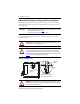
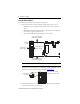
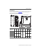
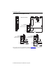
Table Of Contents
- Front Cover
- About the Kinetix 5500 Drives
- Important User Information
- Catalog Number Explanation
- Before You Begin
- Removing the Grounding Screws in Ungrounded Power Configurations
- Install the Kinetix 5500 Servo Drive
- Connector Data
- Wiring Requirements
- Attach the Motor Cable Shield Clamp
- Motor Overload Protection
- Additional Resources
- Back Cover
Kinetix 5500 Servo Drives 9
Rockwell Automation Publication 2198-IN001C-EN-P - January 2014
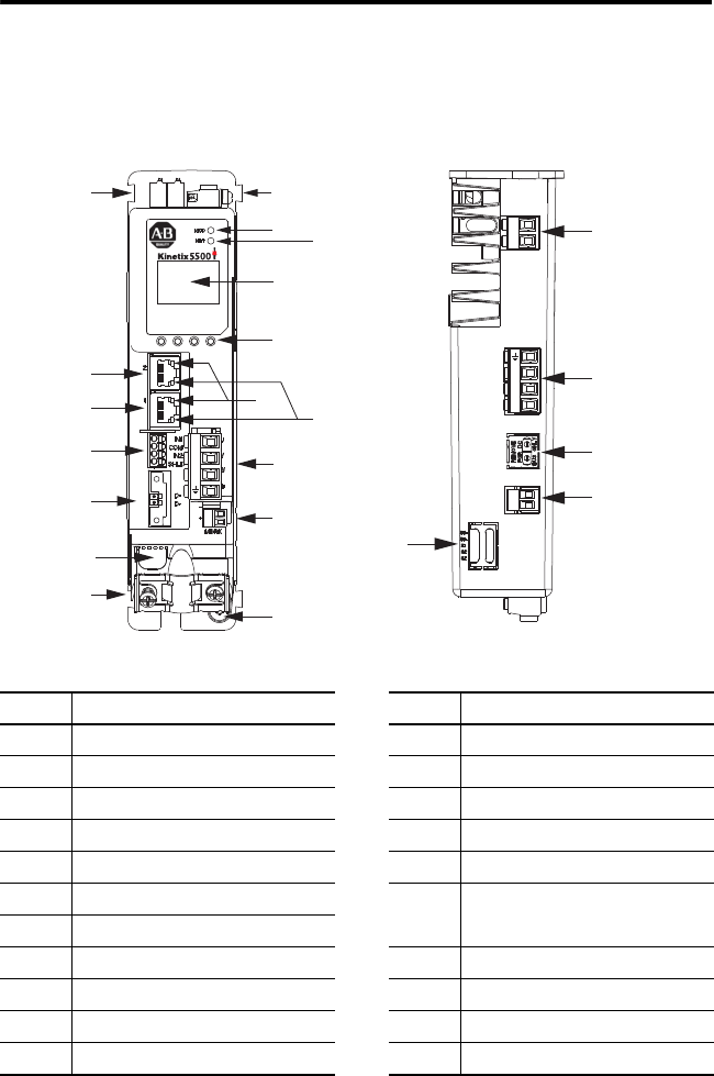
Connector Data
Use this illustration to identify the Kinetix 5500 drive features and indicators.
Kinetix 5500 Drive Features and Indicators
Item Description Item Description
1 Motor cable shield clamp 12 Link speed status indicators
2 Converter kit mounting hole (under cover)
(1)
(1) Protective knock-out covers the 2198-H2DCK converter kit mounting hole. Remove knock-out for use with the converter kit.
13 Link/Activity status indicators
3 Motor feedback (MF) connector 14 Motor power (MP) connector
4 Digital inputs (IOD) connector 15 Motor brake (BC) connector
5 Ethernet (PORT1) RJ45 connector 16 Ground terminal
6 Ethernet (PORT2) RJ45 connector
17
Safe torque-off (STO) connector
(2)
(applies to only 2198-Hxxx-ERS drives)
(2) Protective knock-out cover is removed on 2198-Hxxx-ERS (hard-wired STO) drives.
7 Zero-stack mounting tab/cutout
8 Module status indicator 18 Shunt resistor (RC) connector
9 Network status indicator 19 AC mains input power (IPD) connector
10 LCD display 20 DC bus (DC) connector (under cover)
(3)
(3) DC bus connector ships with protective knock-out cover that can be removed for use in shared-bus configurations.
11 Navigation push buttons 21 24V control input power (CP) connector
17
21
20
19
18
1
2
L3
L2
L1
1
2
+
–
1
8
3
4
13
5
6
11
10
9
12
16
7
7
U
V
W
2
1
15
14
2
Kinetix 5500 Drive, Front View
(2198-H003-ERSx drive is shown)
Kinetix 5500 Drive, Top View
(2198-H003-ERS2 drive is shown)