
Installation Instructions User guide
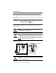
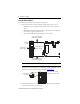
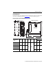
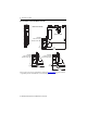
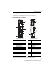
Table Of Contents
- Front Cover
- About the Kinetix 5500 Drives
- Important User Information
- Catalog Number Explanation
- Before You Begin
- Removing the Grounding Screws in Ungrounded Power Configurations
- Install the Kinetix 5500 Servo Drive
- Connector Data
- Wiring Requirements
- Attach the Motor Cable Shield Clamp
- Motor Overload Protection
- Additional Resources
- Back Cover
6 Kinetix 5500 Servo Drives
Rockwell Automation Publication 2198-IN001C-EN-P - January 2014
Mount the Kinetix 5500 Drive
Follow these steps to mount the drive in single-axis configurations.
1. Observe these clearance requirements when mounting a single drive to the panel:
• Additional clearance is required for cables and wires connected to the top of the
drive.
• Additional clearance left and right of the drive is required when mounted adjacent to
noise sensitive equipment or clean wire ways.
• The recommended minimum cabinet depth is 300 mm (11.81 in.).
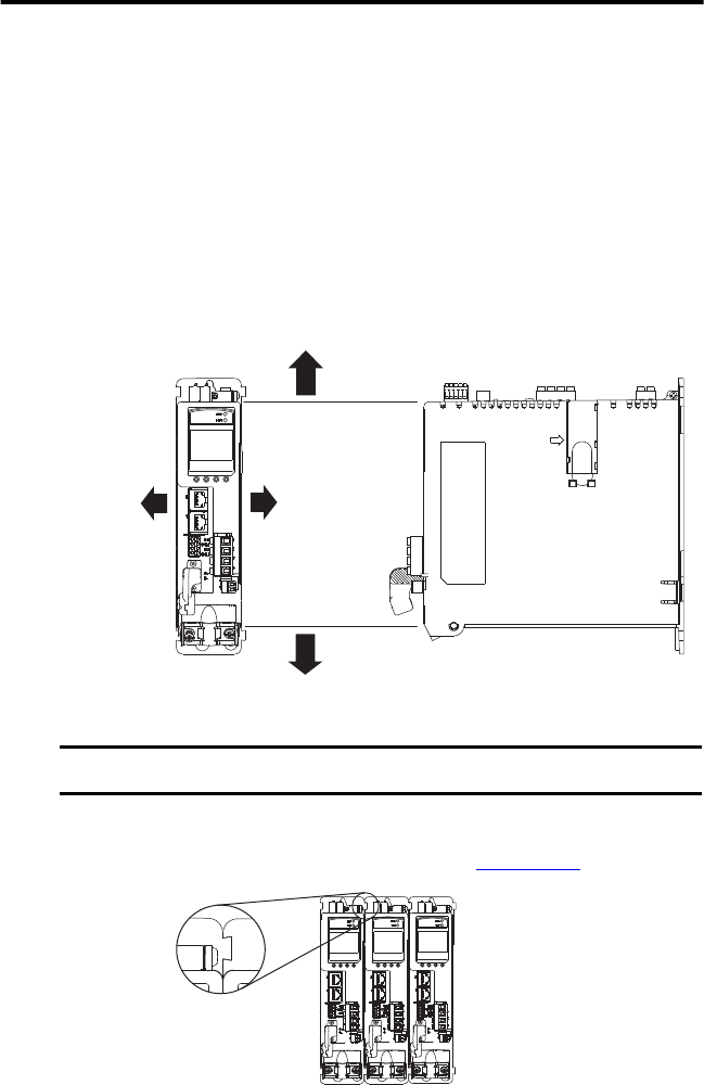
In multi-axis shared-bus configurations, drives must be spaced by aligning the zero-stack
tab and cutout. For mounting, sizing, and configuring shared-bus configurations, refer to
the Kinetix 5500 Servo Drives User Manual, publication 2198-UM001
.
2. Mount the Kinetix 5500 drive to the cabinet subpanel with M4 (#8-32) steel machine
screws torqued to 2.0 N•m (17.7 lb•in), max.
IMPORTANT
Mount the drive in an upright position as shown. Do not mount the drive on its side.
Clearance right of the
drive is not required.
Clearance left of the
drive is not required.
Kinetix 5500
Servo Drive
40 mm (1.57 in.) clearance below
drive for airflow and installation.
40 mm (1.57 in.) clearance above
drive for airflow and installation.
Zero-stack Tab and
Cutout Aligned
Bus-bar system used in bus-sharing
configurations is not shown for clarity.