
Installation Instructions User guide
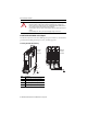
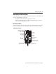
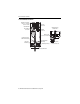
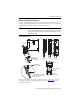
Table Of Contents
- Front Cover
- About the Kinetix 5500 Drives
- Important User Information
- Catalog Number Explanation
- Before You Begin
- Removing the Grounding Screws in Ungrounded Power Configurations
- Install the Kinetix 5500 Servo Drive
- Connector Data
- Wiring Requirements
- Attach the Motor Cable Shield Clamp
- Motor Overload Protection
- Additional Resources
- Back Cover
16 Kinetix 5500 Servo Drives
Rockwell Automation Publication 2198-IN001C-EN-P - January 2014
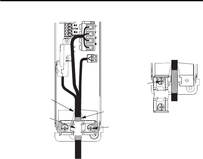
14 and 10 AWG Cable Installation
Motor Cable
Shield Clamp
Motor Power
(MP) Connector
Motor Brake
(BC) Connector
Exposed shield braid
under clamp.
Shield Clamp Screws (2)
Feedback cable routed
within the shield braid.
2198-KITCON-DSL
Motor Feedback
Connector Kit
Retention Screw
(loosen, do not remove)
Clamp features apply
to all frame sizes.
Torque clamp screws to
2.0 N•m (17.5 lb•in), max
Kinetix 5500 Servo Drives,
Frame 2 or 3, Front View
(frame 2 is shown)
Bulletin 2090 Single Motor Cable