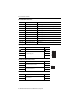
Installation Instructions Kinetix 5500 Servo Drives Catalog Numbers 2198-H003-ERS, 2198-H008-ERS, 2198-H015-ERS, 2198-H025-ERS, 2198-H040-ERS, 2198-H070-ERS, 2198-H003-ERS2, 2198-H008-ERS2, 2198-H015-ERS2, 2198-H025-ERS2, 2198-H040-ERS2, 2198-H070-ERS2 Topic Page About the Kinetix 5500 Drives 1 Important User Information 2 Catalog Number Explanation 3 Before You Begin 3 Removing the Grounding Screws in Ungrounded Power Configurations 4 Install the Kinetix 5500 Servo Drive 5 Connector Data 9
Kinetix 5500 Servo Drives Important User Information Read this document and the documents listed in the additional resources section about installation, configuration, and operation of this equipment before you install, configure, operate, or maintain this product. Users are required to familiarize themselves with installation and wiring instructions in addition to requirements of all applicable codes, laws, and standards.
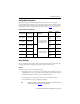
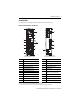
Kinetix 5500 Servo Drives 3 Catalog Number Explanation This publication applies to the following Kinetix 5500 servo drives. For connecting safe torque-off signals, hard-wired drives use the safe torque-off (STO) connector and ship with the protective cover removed. Networked safe torque-off drives do not use the STO connector and ship with the protective cover in place. Refer to Connector Data on page 9 to locate the cover. Kinetix 5500 Drive Catalog Numbers Drive Cat. No. (hard-wired STO) Drive Cat. No.
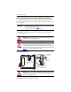
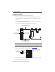
Kinetix 5500 Servo Drives Removing the Grounding Screws in Ungrounded Power Configurations Removing the grounding screw is necessary only when using ungrounded or corner-grounded power configurations. Removing the screws involves gaining access, opening the side door, and removing the screws. IMPORTANT If you have grounded wye power distribution, you do not need to remove the screws. Go to Install the Kinetix 5500 Servo Drive on page 5. Removing the ground screws can affect EMC performance.
Kinetix 5500 Servo Drives 5 Grounding Screw Configurations Ground Configuration (1) Grounding Screw Configuration Benefits of Configuration Grounded (wye) Both screws installed (default setting) • • • • • B-phase corner ground • AC fed ungrounded Both screws removed (1) UL and EMC compliance Reduced electrical noise Most stable operation Reduced voltage stress on components and motor bearings • Helps avoid severe equipment damage when ground fault occurs • Reduced leakage current Refer to the Ki
Kinetix 5500 Servo Drives Mount the Kinetix 5500 Drive Follow these steps to mount the drive in single-axis configurations. 1. Observe these clearance requirements when mounting a single drive to the panel: • Additional clearance is required for cables and wires connected to the top of the drive. • Additional clearance left and right of the drive is required when mounted adjacent to noise sensitive equipment or clean wire ways. • The recommended minimum cabinet depth is 300 mm (11.81 in.). 40 mm (1.
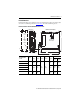
Kinetix 5500 Servo Drives 7 Product Dimensions Included in this figure are the drill hole patterns for standalone drives. Refer to the Kinetix 5500 Servo Drives User Manual, publication 2198-UM001, for multi-axis drill-hole patterns. Kinetix 5500 Drives with 2198-KITCON-DSL Connector Kit Dimensions are in mm (in.) Ø M4 (#8-32) F G 34.00 (1.34) E B 2198-H003-ERS Drive is Shown Applies to Only Frame 3 0.0 0.0 52.50 (2.07) C 3.0 (0.12) A D Drill Hole Patterns Kinetix 5500 Drive Cat. No.
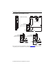
Kinetix 5500 Servo Drives Kinetix 5500 Drives with 2198-H2DCK Converter Kit Dimensions are in mm (in.) Frame 1 Servo Drive 2198-H2DCK Feedback Converter Kit Mounted on Frame 1 Drive 45.0 (1.77) 56.0 (2.20) 2198-H2DCK Feedback Converter Kit Mounted on Frame 3 Drive 2198-H2DCK Feedback Converter Kit Mounted on Frame 2 Drive 56.0 (2.20) 256 (10.08) 256 (10.08) 56.0 (2.20) 256 (10.
Kinetix 5500 Servo Drives 9 Connector Data Use this illustration to identify the Kinetix 5500 drive features and indicators.
Kinetix 5500 Servo Drives Kinetix 5500 Drive Connectors Designator Description Connector IPD AC mains input power 4-position plug, terminal screws DC DC common bus power 2-position (T-connector used in shared-bus configurations) CP 24V control input power 2-position plug, terminal screws RC Shunt power 2-position plug, terminal screws MP Motor power 4-position plug, terminal screws MF Motor feedback 2-position plug, spring terminals BC Brake power 2-position plug, terminal screws
Kinetix 5500 Servo Drives 11 Control Input Power (CP) Connector Pinout Description Signal 1 24V power supply, customer-supplied 24V+ 2 24V common 24V- 1 2 CP Pin Motor Power (MP) Connector Pinout MP Pin Description Signal U Brown Three-phase motor power V Black W Blue U V W Chassis ground Color U V W Green Motor Feedback (MF) Connector Pinout MF Pin (1) Description Signal 1 Bidirectional data and power for digital encoder interface D+ 2 D- Cable shield and grounding plate (in
Kinetix 5500 Servo Drives Safe Torque Off (STO) Connector Pinout STO Pin Description Signal 1 Safety bypass plus signal. This signal is jumped to the safety inputs to enable motion without safety SB+ 2 Safety bypass minus signal. This signal is jumped to safety common to enable motion without safety SB- 3 Safe-stop input channel 1 S1 4 Safe-stop input common SC 5 Safe-stop input channel 2 S2 IMPORTANT Pin 1 The safe torque-off (STO) connector applies to only the 2198-Hxxx-ERS drives.
Kinetix 5500 Servo Drives 13 Kinetix 5500 Drive Power and I/O Wiring Requirements Connects to Terminals Wire Size mm2 (AWG) Strip Length mm (in.) 1.5…4 (16…12) 8.0 (0.31) 2198-H070-ERSx 1.5…6 (16…10) 10.0 (0.39) 2198-H003-ERSx 2198-H008-ERSx 2198-H015-ERSx 2198-H025-ERSx 2198-H040-ERSx Motor power cable depends on motor/drive combination. 0.75…2.5 (1) (18…14) 8.0 (0.31) 2.5…6 (1) (14…10) 10.0 (0.39) Kinetix 5500 Drive Cat. No.
Kinetix 5500 Servo Drives ATTENTION: To avoid personal injury and/or equipment damage, observe the following: • Make sure installation complies with specifications regarding wire types, conductor sizes, branch circuit protection, and disconnect devices. The National Electrical Code (NEC) and local codes outline provisions for safely installing electrical equipment. • Use motor power connectors only for connection purposes. Do not use them to turn the unit on and off.
Kinetix 5500 Servo Drives 15 Attach the Motor Cable Shield Clamp A shield clamp and two screws are supplied with each Kinetix 5500 drive. Use the clamp to bond the motor cable shield-braid to chassis ground. • Routing the conductors with service loops provides stress relief. • Make sure the cable clamp tightens around the cable shield and provides a good bond between the cable shield and the drive chassis.
Kinetix 5500 Servo Drives 14 and 10 AWG Cable Installation Kinetix 5500 Servo Drives, Frame 2 or 3, Front View (frame 2 is shown) 2198-KITCON-DSL Motor Feedback Connector Kit Motor Power (MP) Connector Motor Brake (BC) Connector Clamp features apply to all frame sizes. Retention Screw (loosen, do not remove) Feedback cable routed within the shield braid. Motor Cable Shield Clamp Exposed shield braid under clamp.
Kinetix 5500 Servo Drives 17 Other Allen-Bradley Motors and Actuators For other compatible Allen-Bradley motors and actuators, use the 2198-H2DCK converter kit for wiring motor feedback. A clamp spacer is included with the kit for motor power/brake cable diameters that are too small for a tight fit within the drive clamp alone. IMPORTANT If the power/brake cable shield has a loose fit inside the shield clamp, insert the clamp spacer between the shield clamp and the drive to reduce the clamp diameter.
Kinetix 5500 Servo Drives Motor Overload Protection This servo drive uses solid-state motor overload protection that operates in accordance with UL 508C. Motor overload protection is provided by algorithms (thermal memory) that predict actual motor temperature based on operating conditions as long as control power is continuously applied. However, when control power is removed, thermal memory is not retained.
Kinetix 5500 Servo Drives 19 Additional Resources These documents contain additional information concerning related products from Rockwell Automation. Resource Description Kinetix 5500 Servo Drives User Manual, publication 2198-UM001 Information on installing, configuring, starting, and troubleshooting your Kinetix 5500 servo drive system.
Rockwell Automation Support Rockwell Automation provides technical information on the Web to assist you in using its products. At http://www.rockwellautomation.com/support you can find technical and application notes, sample code, and links to software service packs. You can also visit our Support Center at https://rockwellautomation.custhelp.com/ for software updates, support chats and forums, technical information, FAQs, and to sign up for product notification updates.