
Install External Auxiliary Contact Adapter

Rockwell Automation Publication 2100-IN006B-EN-P - March 2014 3
CENTERLINE Motor Control Centers Install External Auxiliary Contact Adapter
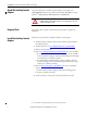
Figure 1 - Left and Right Hand Unit (2100H-N25B)
Figure 2 - Typical Arrangement - Both Positions
#10-32 screws
Left Hand Unit
External Auxiliary
Contact Assembly
#10-32 Screws
External Auxiliary
Contact Assembly
Right Hand Unit
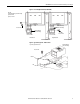
Parts List
(1) External Auxiliary Contact Assembly
(1) Actuator Arm
(4) #10-32 Screws
External Auxiliary
Contact Assembly
#10-32 screws
Actuator
Bail
Top View, Top Plate Removed