
Manual
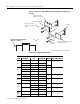


AMP MATERIAL QTY THICKNESS WIDTH SPLICE MTG. HOLES
600
Copper/Tin 1 .125”
3”
2Copper/Silver 1 .125”
Aluminum/Tin 1 .125” 4”
800
Copper/Tin 1 .125”
4” 2Copper/Silver 1 .125”
Aluminum/Tin 1 .1875”
1200
Copper/Tin 1 .250”
4” 2
Copper/Silver 1 .250”
1600
Copper/Tin 2 .250”
4” 4
Copper/Silver 2 .250”
2000
Copper/Tin 1 .250”
4” 4
1 .375”
Copper/Silver 1 .250”
4” 4
1 .375”
2500/
3000
Copper/Tin 2 .375”
4” 4
Copper/Silver 2 .375”
14 CENTERLINE
®
2100 Motor Control Centers Joining and Splicing Vertical Sections
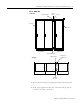
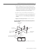
Figure 13 Insulated “Z” 600 - 1200 Amp Bus Splicing Detail and Configuration
Example
Main Horizontal Bus or
Neutral Bus (5” Deeper)
Main Horizontal Splice
One-piece assembly of
nut and conical spring
Bus Clamps
washer
Insulated
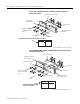
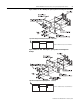
Splice Kit Configuration Example
Front
(Top View - 3 Sections)
Main Horizontal Splice or Neutral
Flat Washers
Bus (standard location)
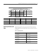
Refer to Table A for bus size and thickness.
Table A Bus and Splice Bar Dimensions
STANDARD NEMA 1, 1G, 12 & 3R SPLICE BAR INFORMATION
Publication 2100-IN010D-EN-P—February 2007