
Instruction Manual


Rockwell Automation Publication 2100-IN012E-EN-P - February 2012 33
Installation Procedures Chapter 2
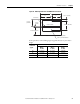
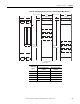
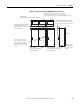
Figure 18 - Mounting Dimensions for 15 in. and 20 in. Deep x 40 in. Wide
Front-mounted Section
The optional external mounting channels add 1.5 in. (38.1 mm) to the height.
Dimensions
approx.
Section Width
(1)
(1) When a horizontal bus or a disconnecting means (switch or circuit breaker) is specified, reduce
the ‘A’ dimension by 5 in. (127 mm).
20 in. Wide
in. (mm)
25 in. Wide
in. (mm)
30 in. Wide
in. (mm)
35 in. Wide
in. (mm)
40 in. Wide
in. (mm)
A 17.25 (438) 22.25 (565) 27.25 (692) 32.25 (819) 37.25 (946)
B 16.50 (419) 21.50 (546) 26.50 (673) 31.50 (800) 36.50 (927)
C 5.25 (133) 7.75 (197) 10.25 (260) 12.75 (324) 15.25 (387)