Installation Instructions CENTERLINE 2100 Low Voltage Motor Control Centers Catalog Number 2100
Important User Information Solid-state equipment has operational characteristics differing from those of electromechanical equipment. Safety Guidelines for the Application, Installation and Maintenance of Solid State Controls (publication SGI-1.1 available from your local Rockwell Automation sales office or online at http://www.rockwellautomation.com/literature/) describes some important differences between solid-state equipment and hard-wired electromechanical devices.
Summary of Changes This manual contains new and updated information. Changes throughout this revision are marked by change bars, as shown to the right of this paragraph. New and Updated Information This table contains the changes made to this revision.
Summary of Changes Notes: 4 Rockwell Automation Publication 2100-IN012E-EN-P - February 2012
Table of Contents Preface About This Publication . . . . . . . . . . . . . . . . . . . . . . . . . . . . . . . . . . . . . . . . . . . . Who Should Use This Manual . . . . . . . . . . . . . . . . . . . . . . . . . . . . . . . . . . . . . Additional Resources . . . . . . . . . . . . . . . . . . . . . . . . . . . . . . . . . . . . . . . . . . . . . . Purchased Components and Additional Instruction Sheets . . . . . . . . . . . 7 7 7 8 Chapter 1 General Information General Description . . . . . . . . . . . .
Table of Contents Chapter 5 Arc Flash Protection Marking as Required by the National Electrical Code Flash Protection Marking Requirement . . . . . . . . . . . . . . . . . . . . . . . . . . . . 61 Arc Flash Marking Clarification . . . . . . . . . . . . . . . . . . . . . . . . . . . . . . . . . . . 62 Rockwell Automation Services . . . . . . . . . . . . . . . . . . . . . . . . . . . . . . . . . . . . 62 Chapter 6 Operator Handle and Unit Interlock Defeating the Unit Door Interlock . . . . . . . . . . . .
Preface About This Publication This manual provides detailed installation instructions for installing, using the operator handle, energizing, and maintaining your CENTERLINE® 2100 Motor Control Center. Who Should Use This Manual This manual is intended for engineers or technicians directly involved in the installation, connection, energizing, and maintenance of the CENTERLINE 2100 Motor Control Center.
Preface Resource Description CENTERLINE Motor Control Centers Installing a Pull Box on a Bulletin 2100 Vertical Section Installation Instructions, publication 2100-5.28 Provides instructions on installing a Pull Box on a motor control center. Safety Guidelines for the Application, Installation, and Maintenance of Solidstate Control Installation Instructions, publication SGI-1.1 Provides safety guidelines for the application, installation, and maintenance of solid-state control.
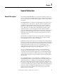
Chapter 1 General Information General Description Allen-Bradley CENTERLINE Motor Control Centers (MCCs) consist of one or more vertical sections containing electromagnetic or solid state control devices that are prewired and tested within modular (plug-in) or frame mounted (hardwired) units. CENTERLINE MCCs are designed in standard widths of 20 in. (508 mm), 25 in. (635 mm), 30 in. (762 mm), 35 in. (789 mm), and 40 in. (1016 mm). The standard front-mounted depths of an MCC are 15 in. (381 mm) and 20 in.
Chapter 1 General Information A label on the MCC with the ArcShield rating provides information in regard to the accessibility level and arc fault ratings. For more information about accessibility levels, performance, and testing requirements, refer to IEEE standard C37.20.7, IEEE Guide for Testing MetalEnclosed Switchgear Rated up to 38 kV for Internal Arcing Faults. MCCs with the ArcShield rating provide a reinforced structure and arccontainment latches on all doors.
General Information Chapter 1 Each plug-in and frame mounted unit also has an identification label. The unit label is on the interior of the bottom plate of plug-in units or on the interior right-hand side plate of the frame mounted units. The unit label for each plug-in or frame mounted unit includes: • catalog number/serial number. • series letter of the unit. • voltage rating. • unit location. • UL and cUL certification marking. • device type and size.
Chapter 1 General Information Sections are numbered to match factory-supplied MCC elevation drawings. Numbering each section helps installers and users easily identify MCCs, sections, and units. If there are questions about section numbering during field installation, inspection, or operation, the following information can provide guidance on equipment acceptability, listing, and certification.
General Information Chapter 1 Vertical sections and structure options that are UL listed and CSA/cUL certified are marked accordingly. All components in a UL or CSA listed section must be UL listed and cUL/CSA certified. The UL and/or CSA/cUL designation is an integral part of the section nameplate as shown on page 11. Units and unit options that are UL listed and CSA/cUL certified are marked accordingly.
Chapter 1 General Information ArcShield Rating Labels MCC units that have the arc resistant rating will carry a rating label on the vertical wireway door. This label serves as the arc resistant nameplate and provides information on the arc resistant rating. There will also be labels on other parts that need to be in place before operating an arc resistant MCC. Figure 7 - ArcShield Labels 100 ms Arc Duration Device Limited Rating ARC RESISTANT EQUIPMENT ARC RESISTANT EQUIPMENT PER IEEE C37.20.
General Information Chapter 1 Table 1 - Sections Series Letter Scope Description of Change Date Implemented in the U.S. M All Changed to serpentine DeviceNet cabling system May 2001 N All New design for 100,000 A bus bracing and begin use of right-hand sidesheet with integral mounting flanges. May 2009 P All New design for bus covers February 2012 (1) Replacement and renewal parts are no longer supported. For more information, contact Rockwell Automation LV MCC Technical Support at 1.440.
Chapter 1 General Information Table 2 - 2100 Units Series Letter Scope Description of Change Date Implemented in U.S.
General Information Series Lettering - Units and Sections Chapter 1 When using sections in conjunction with units of different series letters, consult the table below. Table 4 - MCC Modifications for Unit and Structure Compatibility If Mounted in this Type of Section(1),(2) NEMA Type 1 Series A...D (4) NEMA Type 1 Series E...
Chapter 1 General Information Table 4 - MCC Modifications for Unit and Structure Compatibility If Mounted in this Type of Section(1),(2) Plug-in Units No Additional Parts Required Requires Style 1 Unit Support Pan Requires Style 3 Unit Support Pan Requires Style 3 Unit Support Pan w/ Bushing Requires Alternate Top Horizontal Wireway Pan Requires Requires Requires Door Retrofit Ground Gasketing Kit (3) Bus Kit Kit Space Factor Series — 2100HUAJ1 2100HUA12100H -UJ1 2100HUSPA1 2100HUSPJ1 2100HN
General Information Receiving, Handling, and Storage Chapter 1 Refer to the following sections for information on receiving, handling, and storage of MCC units. Receiving As standard, CENTERLINE MCCs are shipped upright in shipping blocks of one to three front-mounted sections or two to six back-to-back sections. Each shipping block of an MCC is provided with a lifting angle. The lifting angle is optional on NEMA Type 3R and Type 4 MCCs.
Chapter 1 General Information Handling Lifting with a forklift, overhead lifting, sling lifting, and pipe or rod rolling are methods that can be used to handle vertical sections. See the following tables for typical weights and dimensions for standard 20 in. (508 mm) wide and 15 in. (381 mm) or 20 in. (508 mm) deep sections. For sizes not listed, consult your local Rockwell Automation Sales Office. Table 5 - Shipping Weights and Dimensions - Standard Packaging Standard Packing (1) Weight lb (kg), approx.
General Information Chapter 1 Storage and Operation CENTERLINE MCCs conform to NEMA standard ICS 1-2000 for service and storage conditions. All MCCs should operate in an ambient temperature above 0 oC (32 oF) but not exceeding 40 oC (104 oF) at 95% non-condensing humidity. If the equipment is stored, the ambient temperature should remain above -30 oC (-22 oF) but not exceed 65 oC (149 oF). In addition, MCCs have an altitude class of 2 km (1 km for MCCs that contain variable frequency drives).
Chapter 1 General Information Notes: 22 Rockwell Automation Publication 2100-IN012E-EN-P - February 2012
Chapter 2 Installation Procedures Location Planning When planning the location for your CENTERLINE MCC, consider the following: • Conduits • Busways • Overall height of installation area • Alignment with other equipment • Future needs • Ambient temperature The area must be level and the environment must be compatible with the NEMA enclosure rating of the equipment Documentation packages shipped with assembled MCCs include an MCC elevation drawing and an MCC floor plan layout.
Chapter 2 Installation Procedures ArcShield Clearance Height The area above the MCC top plate must be unrestricted to allow for proper operation of the pressure relief venting system. • A minimum clearance above the top of the MCC of 12 in. (305 mm) must be available to allow for pressure relief and/or venting should an internal arcing fault occur.
Installation Procedures Chapter 2 Figure 11 - Mounting Dimensions for 15 in. and 20 in. Sections IMPORTANT The external vertical support angle on MCC sections with 100 ms arcresistant rating add an additional 2 in. (50.8 mm) to each end of the lineup.
Chapter 2 Installation Procedures Figure 12 - Mounting Dimensions for 15 in. and 20 in. Sections - continued (2) Mounting Slots 0.56 in. x 1.13 in. Slots (14 mm x 29 mm) Slots A Standard Ground Bus D D Rear 0.25 in. (6.35 mm) C B 7.38 in. (187 mm) Front E E For seismic bolt-down applications: first section of the MCC lineup. For seismic bolt-down applications: last section of the MCC lineup, extra bolt-down locations (2 bolts). The optional external mounting channels add 1.5 in. (38.
Installation Procedures Chapter 2 Mounting Dimensions for 30 in. and 40 in. Deep Back-to-Back Section 1.69 in. (43 mm) A D D (4) Mounting Slots 0.56 in. x 1.13 in. in Slots (14 mm x 29 mm) Slots Front 7.38 in. (187 mm) C 0.25 in. (6 mm) Rear B 3.19 in. (81 mm) Rear Standard Ground Bus 0.25 in. (6 mm) C 7.38 in. (187 mm) Front Dimensions approx. 20 in. Deep 40 in. Deep 20 in. Wide in. (mm) 25 in. Wide in. (mm) 30 in. Wide in. (mm) 35 in. Wide in. (mm) 20 in. Wide in. (mm) 25 in. Wide in.
Chapter 2 Installation Procedures Figure 13 - Mounting Dimensions for 25 in. Wide Section with 9 in. (228.6 mm) Wireway [90 in. (2286 mm) high] The optional external mounting channels add 1.5 in. (38.1 mm) to the height.
Installation Procedures Chapter 2 Figure 14 - Mounting Dimensions for 10 in. Wide Section with 10 in. (254 mm) Incoming Line Section A (L1) A (L2) A (L3) 7.5 in. (191 mm) 1.25 in. (32 mm) 1.12 in. (28 mm) 10 in. (254 mm) A Power Wires Dimension, approx. B Section Depth 15 in. (381 mm) Deep in. (mm) 20 in. (508 mm) Deep in. (mm) A 12.75 (324) 17.75 (451) B 14.75 (375) 19.
Chapter 2 Installation Procedures Figure 15 - Mounting Dimensions for NEMA 3R and 4 Section [90 in.
Installation Procedures Chapter 2 Figure 16 - Mounting Dimensions for NEMA 3R and 4 Section A B Ground Bus 12.37 in. (314 mm) 2.87 in. (73 mm) C Rear 0.25 in. (6 mm) 16.56 in. (421 mm) Interior Section 14.06 in. (337 mm) Front (2) Mounting Holes 0.63 in. (16 mm) Diameter If the optional non-removal lifting angle is supplied, add 3.63 in. (92.2 mm) to height. Exterior Section Width Dimension, approx. 20 in. (508 mm) Wide(1) in. (mm) 25 in. (635 mm) Wide(1) in. (mm) 30 in. (762 mm) Wide(1) in.
Chapter 2 Installation Procedures Figure 17 - Mounting Dimensions for 15 in. and 20 in. Deep Corner Section [90 in. (2866 mm) high] A 1.41 in. (36 mm) B B A D (2) Mounting Slots 0.56 in. x 1.13 in. in Slots (14 mm x 29 mm) Slots C 0.25 in. (6 mm) (2) Mounting Holes 0.63 in. (16 mm) Diameter D 0.25 in. (6 mm) 1.41 in. (36 mm) Ground Bus C The optional external mounting channels add 1.5 in. (38.1 mm) to the height. Dimension, approx. 32 Section Depth 15 in. (381 mm) Deep in. (mm) 20 in.
Installation Procedures Chapter 2 Figure 18 - Mounting Dimensions for 15 in. and 20 in. Deep x 40 in. Wide Front-mounted Section The optional external mounting channels add 1.5 in. (38.1 mm) to the height. Dimensions approx. Section Width(1) 20 in. Wide 25 in. Wide 30 in. Wide 35 in. Wide 40 in. Wide in. (mm) in. (mm) in. (mm) in. (mm) in. (mm) A 17.25 (438) 22.25 (565) 27.25 (692) 32.25 (819) 37.25 (946) B 16.50 (419) 21.50 (546) 26.50 (673) 31.50 (800) 36.50 (927) C 5.25 (133) 7.
Chapter 2 Installation Procedures Figure 19 - Mounting Dimensions for 15 in. and 20 in. Deep x 40 in. Wide Front-mounted Section 40.00 in. (1016 mm) 10.00 in. (254 mm) 10.00 in. (254 mm) 1.69 in. (43 mm) Rear 0.25 in. (6 mm) B A 7.15 in. (102 mm) Front (4) Mounting Slots 0.56 in. x 1.13 in. in Slots (14 mm x 29 mm) Slots 20.00 in. (508 mm) Standard Ground Bus Dimension, approx. 34 Section Depth 15 in. (381 mm) Deep in. (mm) 20 in. (508 mm) Deep in. (mm) A 15 (381) 20 (508) B 11.
Installation Procedures Chapter 2 Figure 20 - Mounting Dimensions for 71 in. H (reduced height) MCC Sections 0.25 in. (6 mm) 20 in. (508 mm) A 0.25 in. (6 mm) 20 in. (508 mm) D C 70.48 in. (1790.19 mm) 70.48 in. (1790.19 mm) B E 71 in. High Section (1803.4 mm) Dimension, approx. Section Depth 15 in. (381 mm) Deep in. (mm) 20 in.(635 mm) Deep in. (mm) A 15.00 (380) 20.00 (508) B 14.75 (374) 19.75 (500) C 5.12 (130) 10.12 (256) D 4 (101) 8 (203) E — 4.
Chapter 2 Installation Procedures Seismic Requirements To demonstrate the seismic withstand of various CENTERLINE MCCs [20 in. deep (508 mm), 30 in. deep (762 mm) back-to-back, and 40 in. deep (1016 mm) back-to-back], the MCC design construction has been qualified by seismic calculations per the Uniform Building Code (UBC). CENTERLINE 2100 MCC samples have been seismically qualified by dynamic (triaxial multifrequency testing) seismic tests per IEEE 344 Seismic Test Standards.
Installation Procedures Chapter 2 Figure 22 - Seismic Weld Down Requirements 0.25 in. (6 mm) Rear First Section 1.50 in. (38 mm) Second Section and Additional Sections Last Section Front 1.50 in. (38 mm) 1.50 in. (38 mm) 1.50 in. (38 mm) 1.50 in. (38 mm) MCC Lineup Rear Optional Location for Rear Welds 1.50 in.
Chapter 2 Installation Procedures Joining and Splicing MCCs with ArcShield In addition to the horizontal, neutral (if required), and ground bus splicing kits, CENTERLINE MCCs with arc-resistant ratings have these additional requirements: • MCCs with the 100 ms arc-resistant rating have a back-corner baffle at the end of each lineup and insulation on the side closing-plate at the end of the lineup. They also have external vertical support angles at each end of the lineup.
Installation Procedures Chapter 2 Figure 23 - Joining Instructions for NEMA Type 3R and 4 Sections (2) wireway extensions required for 15 in. (381 mm) deep. (2) wireway extensions required for 20 in. (508 mm) deep. (1) 0.25 in. (6 mm) -20 x 0.70 in. (17.78 mm) taptite per wireway extension. Cabinet Spacer (2) 0.25 in. (6 mm) x 0.50 in. (12.7 mm) Taptites MCC MCC MCC Remove left-hand driphood angle and remount after the adjacent driphood has been drilled out. (2) 0.25 in. (6 mm) x 0.50 in. (12.
Chapter 2 Installation Procedures Bus Torque Specifications Tighten all bus splice connections with a torque wrench and socket at intervals established by your maintenance policy. See Chapter 9 for suggested maintenance. If a torque wrench is not available, tighten until the conical spring washer is flat. Torque values can be found on the information label on the interior of the vertical wireway door or on the interior right-hand side plate of frame mounted units.
Chapter 3 Installing Conduit and Cable Installing Conduit When installing conduit, make sure it is installed according to local codes - to assure water and moisture cannot enter or accumulate in the MCC enclosure. Conduit must be installed so they are compatible with the NEMA rating of the MCC. The conduit should be placed away from the horizontal ground bus to avoid damage.
Chapter 3 Installing Conduit and Cable 1. After the MCC is in place, leveled, and the sections are joined and spliced, bring conduit into the top of the incoming section. For approximate top entry locations and wiring schemes for main fusible disconnects, main circuit breakers and incoming line compartments, refer to Mains and Incoming Lines Dimension Reference, publication 2100-TD018. 2. Remove the lifting angle and top plate. 3. Modify the top plate for necessary conduit entries.
Installing Conduit and Cable Chapter 3 Incoming Line Compartment Top or bottom entry to the incoming line-section bus is straight through to the connection terminals. The vertical bus provides pads for the incoming lugs. The lug selection should be based on the size, number, and type of conductor. • Use of mechanical screw-type lugs is acceptable only when the incoming lines’ available short-circuit current is 42,000 A rms symmetrical or less.
Chapter 3 Installing Conduit and Cable Securing Cables with Glass Tape In this example, glass fiber-reinforced tape or glass filament tape is used. The taping should be continuous from the point the cables enter the MCC to the point the cables are terminated. It is important that cables are wrapped several times for additional strength. Cable slack should be drawn up during wrapping so that individual cables are supported by the tape as a single mass.
Installing Conduit and Cable Chapter 3 Securing Cables with Hardwood In this example, a hardwood brace (maple hardwood) made for the specific application is used. Holes are bored approximately the size of the cable diameter. Several bolt holes are also bored the breadth of the hardwood brace. The brace is cut in two pieces and is used as a clamp to secure the cables. Through bolts are inserted into the brace and tightened so that cables are held tightly in place.
Chapter 3 Installing Conduit and Cable Notes: 46 Rockwell Automation Publication 2100-IN012E-EN-P - February 2012
Chapter 4 Installing and Removing Plug-in Units ATTENTION: When installing or removing MCC units, when possible, deenergize, lockout, and tag-out all sources of power to the MCC. If the MCC units will be installed or removed with power applied to the main power bus, follow established electrical safety work practices. Refer to the NFPA 70E Standard for Electrical Safety in the Workplace publication. ATTENTION: Review your company safety lockout and tag-out procedure.
Chapter 4 Installing and Removing Plug-in Units Remove a SecureConnect Unit from a Section Follow these steps to remove a SecureConnect™ unit from a section. 1. Make sure the disconnect handle is in the OFF/O position. 2. Slide the shaft port cover open. 3. Insert the 1/4 in. hex tool into the shaft port. 4. Rotate the wrench counter-clockwise to retract the power stabs. The indicator next to the disconnect handle changes from red to green. Indicator Shaft Port Shaft-port Cover Open Closed 5.
Installing and Removing Plug-in Units Chapter 4 7. Connect a multi-meter to the status port to verify that there is a closed connection. Status Port Stab Lockout a. Verify that the stabs are retracted by checking the continuity in pins 1 and 2. When the stabs are retracted, they complete the circuit verifying that all three stabs have retracted completely. b. Verify that the stab housing shutters are closed by checking continuity in pins 3 and 4 of the status port.
Chapter 4 Installing and Removing Plug-in Units Remove a Plug-in Unit with a Vertical Operating Handle from a Section 1. Make sure the disconnect handle is in the OFF/O position. 2. For non-arc resistant units, turn the door latches 1/4 turn; for units that are equipped with arc-resistant door latches, push in the latch and rotate 1/4 turn.
Installing and Removing Plug-in Units Chapter 4 3. Open the door completely. 4. Remove the unit door, if necessary. TIP It is not necessary to remove the unit door to remove a unit from a section. However, these steps may still be necessary even when the door is not removed. a. Remove the door-mounted devices and wiring, if necessary. b. Remove the hinge pins by sliding upward with a flathead screwdriver.
Chapter 4 Installing and Removing Plug-in Units The control station can be hung on the front of the unit by using square holes adjacent to the top unit latch. c. Swing the door to near closed position. d. Lift the door outward to remove. 5. Disengage the captive latches at the front of the unit, one at the top and one at the bottom of the unit. Units that are 2.0 space factor and larger have two latches at the top. All units with the 100 ms arc-resistant rating have two latches at the top.
Installing and Removing Plug-in Units Chapter 4 7. Remove other cables or devices that would prevent the unit from being withdrawn. TIP It is not necessary to place wires and terminal blocks into the vertical wireway to remove a plug-in unit that includes the wiring clearance tunnel. . 8. Pull the unit forward (outward) approximately 3 in. (7.5 cm) out of the MCC, using the handle provided at the lower left of the unit and the tab in the upper right of the unit as finger holds.
Chapter 4 Installing and Removing Plug-in Units For the CENTERLINE 2100 MCC units with arc-resistant door latches, you may need to tilt the top of the unit slightly to the rear to avoid interference with the top arc latch bracket before removing the unit. If you do not have enough clearance, you will need to loosen the latch bracket screw (approximately two turns) to remove the unit.
Installing and Removing Plug-in Units Chapter 4 Remove a Plug-in Unit with a Horizontal Operating Handle from a Section 1. Make sure the disconnect handle is in the OFF/O position. 2. For non-arc resistant units, turn the door latch 1/4 turn; for units that are equipped with arc-resistant door latches, push in the latch and rotate 1/4 turn. Arc Containment Latch 3. Open the door completely. 4. Remove the unit door, if necessary.
Chapter 4 Installing and Removing Plug-in Units b. Remove the hinge pins by sliding upward with a flathead screwdriver. For Units With Follow This Step A control station First slide the hinge pin out of the hinge and through the tab on the control station wiring. ArcShield units with 100 ms arc duration rating Two hinges are required for each hinge leaf. Only top hinge must be removed to install hinge pin. 1.
Installing and Removing Plug-in Units Chapter 4 5. Detach the wiring/terminal block from the unit. 6. Place the wiring/terminal block in the vertical wireway to the right of unit. 7. Push the latch mechanism to the left with your right hand. 8. Pull the unit forward (outward) approximately 3 in. (7.62 cm) out of the MCC. You may need to reposition your hands as necessary to properly support the unit while you are removing the unit from the MCC.
Chapter 4 Installing and Removing Plug-in Units For the CENTERLINE 2100 MCC units with swing-out door latches, you will need to rotate the latch bracket 90o clockwise to avoid interference with the unit. Swing-out Latch Bracket ATTENTION: Plug-in MCC units may be heavy or awkward to handle. Use an assistant or a platform lift device if necessary to help you handle the unit. 9. Remove the unit from the MCC. 10. Carefully install protective caps or close the manual shutters after unit is removed.
Installing and Removing Plug-in Units Remove the Support Pan Chapter 4 1. For ArcShield sections with 100 ms arc duration rating, remove the vertical wireway baffle and set aside for installation later. 2. Pry the plastic retaining clip from the right-hand unit support by using a screwdriver. This is visible in the vertical wireway.
Chapter 4 Installing and Removing Plug-in Units For CENTERLINE MCC units with the 100 ms arc duration rating, there is an additional screw that secures the unit support pan. This screw is at the left-rear corner of the unit support pan. Unit Support Pan Unit Support Pan Screw 3. Lift the right side of the support pan approximately 4 in. (102 mm). 4. Pull the right side of the support pan forward to release from the left rear slot on the structure. 5.
Chapter 5 Arc Flash Protection Marking as Required by the National Electrical Code Flash Protection Marking Requirement The flash protection marking requirement was initially established in 2000 by The National Fire Protection Association (NFPA 70E), Standard for Electrical Safety Requirements for Employee Workplaces. NFPA 70E applies to workers who install, maintain, or repair electrical systems. In 2002, NFPA 70, The National Electrical Code (NEC) added the Article 110.
Chapter 5 Arc Flash Protection Marking as Required by the National Electrical Code Arc Flash Marking Clarification The flash protection marking per NEC Article 110.16 is a field marking requirement and is to be applied by the MCC end-user for each specific application. The marking is similar to other NEC marking requirements, for example, voltage, voltage hazard labels, and circuits. However, flash protection markings must be based on application information and calculations from the installation site.
Chapter 6 Operator Handle and Unit Interlock The operator handle is an integral part of each MCC unit. Adjustment of the handle is not required. The operator handle is interlocked with each unit door as outlined by UL 845. Defeating the Unit Door Interlock Refer to the following information for defeating the unit door lock.
Chapter 6 Operator Handle and Unit Interlock Figure 27 - Operating Handle Defeater for Vertical Operator Handle Figure 28 - Operating Handle Defeater for Horizontal Operator Handle Defeating the Unit Interlock Lever 64 Refer to the following information for defeating the unit interlock lever.
Operator Handle and Unit Interlock Chapter 6 Energize a Unit with the Unit Door Open ATTENTION: When working on or near energized electrical equipment, follow established electrical safety-related work practices. Refer to NFPA 70E Standard for Electrical Safety in the Workplace. Personal protective equipment (PPE) is not shown for clarity.
Chapter 6 Operator Handle and Unit Interlock Figure 30 - Defeater Lever for Horizontal Operating Handle Locking Provisions Refer to the following sections for locking provisions. Lock Vertical Operating Handles in the OFF/O Position ATTENTION: When working on or near energized electrical equipment, follow established electrical safety-related work practices. Refer to NFPA 70E Standard for Electrical Safety in the Workplace.
Operator Handle and Unit Interlock Chapter 6 Lock Horizontal Operating Handles in the OFF/O Position Some units use a horizontal operating handle. The horizontal operating handle can be locked in the OFF/O position by putting the shackle of the lock through the open slotted area to the left of the operator handle.
Chapter 6 Operator Handle and Unit Interlock Figure 33 - Locking Small Handle in ON/I POSITION, Vertical Operating Handle Drill Out Figure 34 - Locking the Medium Handle in ON/I Position Drill Out 68 Rockwell Automation Publication 2100-IN012E-EN-P - February 2012
Operator Handle and Unit Interlock Chapter 6 Figure 35 - Locking Large Handle in ON/I Position Drill Out Figure 36 - Locking Horizontal Handle in ON/I Position Drill Out Unit Interlocks A unit interlock is provided with each plug-in unit. Unit interlocks prevent units from being removed from or inserted into a vertical section when the operator handle is in the ON/I position.
Chapter 6 Operator Handle and Unit Interlock Units can also be locked out with a padlock preventing installation of the unit into a vertical section. The lockout feature of the unit interlock can be used with a padlock to keep the interlock in an extended position, which will prevent the unit from being inserted into an MCC section. The unit interlock can also be used with the unit installed in the section, but partially removed from the section.
Operator Handle and Unit Interlock Chapter 6 Figure 38 - Unit Interlock to Prevent Insertion - Unit Completely Withdrawn In this position, the unit is partially removed from the MCC and the intermediate slot in the interlock plate is in line with the bushing in the unit support pan. When the unit is locked in this position, the unit power and ground stabs are disengaged. This position can be used to prevent insertion of a unit into the MCC.
Chapter 6 Operator Handle and Unit Interlock ATTENTION: When working on or near energized electrical equipment, follow established electrical safety-related work practices. Refer to NFPA 70E Standard for Electrical Safety in the Workplace. We recommend that maintenance performed on the MCC units be performed away from the MCC in a suitable work area, when possible.
Chapter 7 Final Checklist Before Energizing Introduction This section provides guidance for the startup of a newly installed MCC. We recommend making an itemized list including: • serial number. • number of sections. • number of units and their corresponding voltage. • current ratings. • horsepower ratings • types of circuits. • fuse sizes. • circuit breaker ratings and trip settings. • heater elements requirements. • arc resistant components. • other important data.
Chapter 7 Final Checklist Before Energizing Perform the Pre-energizing Check Procedure ATTENTION: To ensure the safety of personnel performing the preenergizing check, make sure the MCC remote power sources are disconnected and locked in the OFF/O position. Using a voltmeter, verify that the MCC remote power sources are disconnected. ATTENTION: Power factor correction capacitors (PFCCs) should be applied correctly.
Final Checklist Before Energizing Chapter 7 The factory-made power bus connections are tightened by a computercontrolled torquing system. The following connections do not require retorquing: • vertical to horizontal bus connections. • power conductor to horizontal bus connections. These factory-made horizontal to vertical bus connections do not require servicing for the life of the MCC. 6. Check and verify that all ground connections are made properly, based on local standards.
Chapter 7 Final Checklist Before Energizing 8. Check that the voltage and horsepower ratings on the motor correspond with the MCC unit ratings. 9. Check that the overload relays or heater elements are selected, installed and/or adjusted to relative full load current shown on the motor rating nameplate. 10. For applications requiring power fuses, install the fuses in the fusible switches in accordance with the NEC application requirements.
Final Checklist Before Energizing Chapter 7 13. Manually exercise all switches, control auxiliary switches, circuit breakers, their respective operators, unit interlocks, trip mechanisms (test by pushing the ‘Push to Trip’ button), and any other operating mechanisms to verify proper operation. 14. Check timing relay settings as required. 15. Check the vents and fans. a. Check all vents to ensure they are free from obstructions. b.
Chapter 7 Final Checklist Before Energizing Conduct this test using an insulation resistance tester (megger) with a potential of 500…1000V. This megger test should be conducted phase-tophase, phase-to-ground, and when applicable, phase-to-neutral on the MCC buswork. The test should be conducted with all of the switches or circuit breakers in the open or OFF/O positions. Typical insulation resistance values are 50 MΩ or greater.
Final Checklist Before Energizing Chapter 7 Door Latch Position Diagrams Figure 41 - Vertical Wireway Door Standard Latches Arc Resistant Latches Figure 42 - 0.5 Space Factor and Units with Horizontal Disconnect Handles 0.
Chapter 7 Final Checklist Before Energizing Figure 43 - 1.0 Space Factor and Units with Vertical Disconnect Handles 1 Space Factor to 2.5 Space Factor An arc resistant latch is used for the center latch only for main incoming power units and 100 ms arc-resistant rating. 2.5 Space Factor or Larger Standard Latches Arc Resistant Latches For most units, the center latch is a standard quarter-turn latch. For some units a multi-turn latch is used. Torque the latch to 20 lb•in +/- 2 lb•in.
Final Checklist Before Energizing Chapter 7 Figure 44 - 6 Space Factor (full section) Units An arc resistant latch is used for the second and fourth positions. Other latches are standard quarter turn. All center latches are arc-resistant latches for units with 100 ms arcresistant rating. Standard Latches Arc Resistant Latches When properly latched, the slots on all arc resistant latches are vertical and the latch springs are compressed. The spacing of the spring coils are decreased.
Chapter 7 Final Checklist Before Energizing ArcShield Components Checklist ATTENTION: Arc resistant CENTERLINE 2100 MCCs are provided with certain components to achieve the arc-resistant rating. These components must be in place prior to using the MCC in order to maintain the arc resistant capabilities. TIP Not all of the components and features necessary for the arc-resistant rating are shown in these images. Figure 46 - Arc-resistant MCC with Insulating Sheet (15 in.
Final Checklist Before Energizing Chapter 7 Figure 47 - ArcShield Components Pressure Relief Vent (100 ms ArcShield rating only) Vertical Support Angle (end of lineup) WARNING HOT GASES MAY BE EXHAUSTED IF AN INTERNAL ARCING FAULT OCCURS. 41006-404-01 (1) ArcShield Rating Label Device Limited 100 ms Rating Rating ArcShield Door Latches ARC RESISTANT EQUIPMENT ARC RESISTANT EQUIPMENT PER IEEE C37.20.7 2007 PER IEEE C37.20.
Chapter 7 Final Checklist Before Energizing SecureConnect Unit Checklist Verify these items before using a SecureConnect unit. 1. Make sure the stab lockout is pushed in. 2. Verify the disconnect handle is OFF/O. 3. Insert the tool in the shaft port and rotate the tool to the right. The status indicator should change from green to red. Status Indicator Shaft Port Status Port Stab Lockout ATTENTION: SecureConnect units are shipped inside the unit location with stabs in the disconnected position.
Final Checklist Before Energizing Required Minimum Electrical Spacing Chapter 7 . Table 7 - Electrical Spacing Requirements for MCCs(1) Min Spacing, in. (mm) Between Live Parts of Opposite Polarity Voltage Through Air Over Surface Between Live Parts and Grounded Metal Parts, Through Air and Over Surface 0…150 0.5 in. (12.7 mm) 0.75 in. (19.1 mm) 0.5 in. (12.7 mm) 151…300 0.75 in. (19.1 mm) 1.25 in. (31.8 mm) 0.5 in. (12.7 mm) 301…600 1.0 in. (25.4 mm) 2.0 in. (50.8 mm) 1.0 in. (25.
Chapter 7 Final Checklist Before Energizing Figure 48 - Sample MCC Layout Worksheet Horizontal Wireway 1.0 S.F. 113 in.
Final Checklist Before Energizing Chapter 7 Table 10 - Unit Description Unit Type Code Code Description CN2DN ControlNet to DeviceNet DNC DeviceNet Connector DNPS DeviceNet Power Supply EN2DN Ethernet to DeviceNet FCBX Insert with Circuit Breaker FDSX Insert with Fusible Disconnect FVLC Full Voltage Lighting Contactor FVR Full Voltage Reversing FVNR (V) Full Voltage Non-Reversing (Vacuum) INSRT Unit Insert LPAN Lighting Panel (M)BPS MAIN Bolted Pressure Switch (M)CB MAIN Circuit
Chapter 7 Final Checklist Before Energizing Table 11 - MCC Layout Worksheet MCC Name / Number ___________________________________________________________ 88 Rockwell Automation Publication 2100-IN012E-EN-P - February 2012 Power Fuse Rating Circuit Breaker Trip Setting Kilowatts Overload or Heater Elements Horsepower Full Load Current Wiring Diagram Description Cat. No.
Final Checklist Before Energizing Chapter 7 Table 12 - Megger Reading Recording Table MCC Name / Number ___________________________________________________________ Date Circuit / Unit Name / Number Phase-to-Phase A-B B-C Phase-to-Ground C-A A - Grd. B - Grd. Phase-to-Neutral C - Grd. Rockwell Automation Publication 2100-IN012E-EN-P - February 2012 A - Neut. B - Neut. C - Neut.
Chapter 7 Final Checklist Before Energizing Notes: 90 Rockwell Automation Publication 2100-IN012E-EN-P - February 2012
Chapter 8 Energizing the Equipment ATTENTION: This procedure is provided as general guidance for energizing a newly installed CENTERLINE MCC and should be used after the Final Check procedure has been completed. See Final Checklist Before Energizing for more information. ATTENTION: Energizing a MCC for the first time is potentially dangerous. Serious damage and or personal injury can result when power is applied. Therefore, only qualified personnel should energize the equipment.
Chapter 8 Energizing the Equipment a. When power-factor correction capacitors are energized with the motor windings and the start-up procedure requires that the respective motors be jogged or inched, temporarily disconnect the power factor correction capacitors. For more information on power factor capacitors and MCC units, refer to the Power Factor Correction Capacitors for Bulletin 2100 Motor Control Center Starter Units Application Techniques, publication 2100-AT001. b.
Chapter 9 Maintenance Establish a periodic maintenance program for MCCs to avoid unnecessary downtime. The frequency of service to the MCC will depend upon the equipment usage and the environment in which it operates. The following is a suggested checklist and can be used to establish a maintenance program. ATTENTION: De-energize the MCC before servicing. Maintain the MCC 1. Inspect the MCCs once per year or per established maintenance program. 2.
Chapter 9 Maintenance 5. Periodically clean or replace the air filters depending on the environmental conditions. 6. Check for the proper function and freedom of movement (no sticking or binding) for the disconnect handle operating and defeater mechanisms. 7. Replace broken, deformed, malfunctioning, or badly worn parts or assemblies. 8. Inspect unit bus-stab connections for wear or corrosion.
Maintenance Chapter 9 14. Check contactor and relay coils for evidence of overheating, such as cracking, melting, or burning of insulation. If there is evidence of overheating, the coil must be replaced. When replacing a coil, check and correct the overvoltage or undervoltage conditions that may have caused the coil failure. Be sure to clean any residue of melted coil insulation from other parts of the device and replace as necessary. 15.
Chapter 9 Maintenance 1. Determine your unit type. Plug-in Units If a disconnect switch requires lubrication and is housed in a plug-in unit, remove the plug-in unit from the MCC (For removal of unit, refer to 4, Installing and Removing Plug-in Units, before lubricating the switch). Frame Mounted Units If a disconnect switch requires lubrication and is housed in a frame mounted unit, turn off the power sources to the MCC so the switch can be lubricated.
Maintenance Use Thermal Infrared or Other Temperature Measurement Techniques for Preventive Maintenance Chapter 9 ATTENTION: Temperature measuring techniques are often performed with the units fully energized and the doors and covers open. Use extreme caution when performing these measurements so that energized parts are not shorted. If care is not taken, electrical shock, severe injury or death will result.
Chapter 9 Maintenance ATTENTION: To service the units, make sure that the MCC remote power sources are disconnected and that the respective disconnects are locked in the OFF/O position. If servicing a plug-in unit, remove it from the MCC to facilitate servicing. Refer to Chapter 2 of this publication for unit removal guidelines.
Chapter 10 Maintenance After Fault Condition Maintain the MCC After a Fault Condition ATTENTION: Make sure that the MCC remote power sources are disconnected and that the respective disconnects are locked in the OFF/O position. The opening of the short circuit protective device (such as fuses or circuit breakers) in a properly coordinated motor branch circuit is an indication of a fault condition in excess of operating overload and must be corrected.
Chapter 10 Maintenance After Fault Condition Notes: 100 Rockwell Automation Publication 2100-IN012E-EN-P - February 2012
Chapter 11 Renewal Parts A Renewal Parts Stocking Program for MCCs is recommended in conjunction with a maintenance program. This is important for minimizing expensive downtime and to be able to facilitate critical repairs. Factors to consider when developing an effective Renewal Parts Stocking Program include the following: • The frequency of ON-OFF cycling and the amount of ON or operating time.
Chapter 11 Renewal Parts Notes: 102 Rockwell Automation Publication 2100-IN012E-EN-P - February 2012
Chapter 12 Parts Illustrations Typical Section Construction Lifting Angle Removable Top Plate Top Horizontal Wireway Baffle Top Horizontal Wireway Cover Left Hand Top End Closing Plate Right Hand Unit Support Vertical Wireway Assembly Horizontal and Vertical Bus Support Bus Splice Access Cover Vertical Power Bus Section Nameplate Horizontal Power Bus Vertical Wireway Door Vertical to Horizontal Bus Connection Access Cover Left Hand Center End Plate Vertical Bus Support Cover Vertical Plug-in Gro
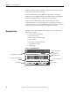
Chapter 12 Parts Illustrations Typical Construction of a Unit with a Vertical Operating Handle Captive Latch Diagram Pocket Starter or Contactor Unit Stab Assembly Control Circuit Fuses and Fuse Block Unit Handle Interlock Circuit Breaker or Fusible Disconnect (shown) Auxiliary Contacts Overload Disconnect Handle Control Circuit Transformer (not shown) Control Transformer Fusing and Fuse Block Defeater Mechanism Power and Control Terminal Blocks Short Circuit Rating Label Unit Identification Na
Parts Illustrations Chapter 12 Typical Construction of a Half Space Factor Unit with a Horizontal Operating Handle and Door Mounted Pilot Devices Control Circuit Transformer Unit Stab Assembly Contactor or Starter Overload Relay Control Circuit Fuse block and Fuses Circuit Breaker (shown) or Fusible Disconnect Handle Mechanism Unit Latch/Interlock Control Terminal Block Starter Unit Nameplate Unit Door Pilot Devices Unit Support Pan Unit Support Pan Bushing Rockwell Automation Publication 2100-
Chapter 12 Parts Illustrations Typical Construction of a Unit with a Horizontal Operating Handle Control Circuit Transformer Unit Stab Assembly Contactor or Starter Overload Relay Circuit Breaker (shown) or Fusible Disconnect Control Circuit Fuse block and Fuses Control Terminal Block Handle Mechanism Unit Latch/Interlock Pilot Devices Auxiliary Contacts Unit Nameplate Unit Door Unit Support Pan Unit Support Pan Bushing Plastic Retaining Pin Bulletin 2413, IEC Style Shown 106 Rockwell Automati
Index A adding sections 12 additional resources 7 air filter check 94 air filters 77 altitude class 21 arc flash 63 protection marking requirement 61 Rockwell Automation services 62 ArcShield 9, 14 components checklist 82 door hinge removal 51, 56 door latch positions 79 IEEE 10 insulating sheet 82 joining and splicing 38 opening door 50, 55 pressure relief plate 24 rating 54, 58 rating label 14 section clearance 24 support pan removal 59, 60 top entry conduit 41 unit removal 54 conduit 41 bottom entry 41
Index lugs 42 plug-in units 47 vertical handle 47 interlocking devices check 94 J joining and splicing 37 bus torque 40 joining and splicing NEMA Type 12 motor control centers 38 joining and splicing NEMA Type 3R and Type 4 units 38 L labels ArcShield 14 short circuit rating 13 UL 13 layout worksheet 86 lifting angle 24 lifting sections 20 line compartment 43 location planning 23 locking horizontal handle 69 horizontal operating handle 67 large vertical handle 69 medium vertical handle 68 padlock 70 smal
Index product overview 9 publications 7 pull boxes 38 Q qualified persons 73 R rearranging sections 12 receiving 19 remove support pan 59 remove units horizontal handle 55 SecureConnect 48 vertical handle 50 removing large units 53, 58 renewal parts 101 S sections adding 12 installation 12 lifting 20 numbering 12 rearranging 12 SecureConnect 48 seismic requirements 36 bolt down 36 IEEE 344 36 weld down 37 sequence numbering 11 series lettering 17 number and series ID 14 shipping weights 20 export 20 sta
Index Notes: 110 Rockwell Automation Publication 2100-IN012E-EN-P - February 2012
Rockwell Automation Support Rockwell Automation provides technical information on the Web to assist you in using its products. At http://www.rockwellautomation.com/support/, you can find technical manuals, a knowledge base of FAQs, technical and application notes, sample code and links to software service packs, and a MySupport feature that you can customize to make the best use of these tools.