
Owner manual


Rockwell Automation Publication 20Y-UM001E-EN-P - July 2014 75
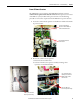
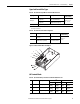
AFE in IP21 Rittal Enclosure—Installation/Wiring Chapter 2
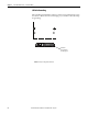
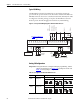
Table 17 - I/O Terminal Designations for AFE in IP21 Rittal Enclosure
ATTENTION: For the AFE in the IP21 Rittal enclosure, Digital Inputs 1, 3, 4, and
5, and Digital Outputs 1 and 2 are factory wired and programmed to operate
from the controls on the front of the enclosure. Digital Output 3 is
programmable and factory wired for +24V DC only. Do not change the wiring
and programming for those digital inputs and outputs, or it will result in
malfunction of the system.
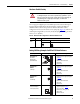
No. Signal Factory Default Description
1Analog In 1 (–)
(1)
(1) Important: Input must be configured with a jumper. AFE damage can occur if jumper is not installed properly. See Analog I/O
Configuration on page 76.
(2)
(2) These inputs/outputs are dependant on a number of parameters.
Isolated
(3)
, bipolar, differential, 9 bit & sign,
88k ohm input impedance. A jumper (see
Table 18) selects 0-10V, ±10V, or 4-20 mA.
Default: 0-10V (Ri = 200k ohm), 4-20 mA
(Ri = 100 ohm).
(3) Differential Isolation - External source must be maintained at less than 160V with respect to PE. Input provides high common mode
immunity.
2Analog In 1 (+)
(1)
3Analog In 2 (–)
(1)
4Analog In 2 (+)
(1)
5 –10V Pot Reference — 2k ohm min, 10 mA max load, 1% accuracy
6 Pot Common (GND) For (+) and (–) 10V pot references
7 +10V Pot Reference — 2k ohm min, 10 mA max load, 1% accuracy
8Analog Out 1 (+)
(2)
Bipolar (current out is not bipolar), 9 bit and
sign, 2k ohm min load. A jumper (see
Table 18) selects 0-10V, ±10V, or 4-20 mA.
9 Analog Out Common
10 Analog Out 2 (+)
11 Digital In 1 RunCmd 24V DC
- Opto isolated (250V)
Low State: less than 5V DC
High State: greater than 20V DC, 11.2 mA
DC
Enable
: Digital Input 6 is jumper selectable
for HW Enable.
On-Time: < 16.7 ms, Off-Time < 1 ms
12 Digital In 2 Ext. Reset
13 Digital In 3 Enable Mcont
14 Digital In 4 Contactor Ack
15 Digital In 5 LCL Temp
16 Digital In 6/Hardware
Enable, see page 77
17
18
Digital In Common Allows source or sink operation
19 +24V DC
(4)
(4) 150 mA maximum load. Can be used to provide control power from an external 24V source when main power is not applied.
— Unit supplied logic input power
20 24V Common
(4)
— Common for internal power supply
21 Digital Out 1 – N.C.
(5)
(5) Contacts in un-powered state. Any relay programmed as Fault or Alarm energizes (pick up) when power is applied to the AFE, and
de-energizes (drop out) when a fault or alarm exists. Relays selected for other functions energize only when that condition exists
and de-energizes when the condition is removed.
Contact Ctrl Max. Resistive Load:
240V AC/30V DC – 1200VA, 150W
Max. Current: 5A, Min. Load: 10 mA
Max. Inductive Load:
240V AC/30V DC – 840VA, 105W
Max. Current: 3.5A, Min. Load: 10 mA
NOTE: See the Attention above this table
for more details.
22 Digital Out 1 Common
23 Digital Out 1 – N.O.
(5)
24 Digital Out 2 – N.C.
(5)
Fault
25 Digital Out 2/3 Com.
26 Digital Out 3 – N.O.
(5)
(6)
(6) When this output is configured as active, it can be wired to the Enable input of the connected drives to prevent the AFE from
supplying power when the AFE is not running.
Active
1
10
20
21
26