
Owner manual

Rockwell Automation Publication 20Y-UM001E-EN-P - July 2014 53
AFE in IP21 Rittal Enclosure—Installation/Wiring Chapter 2
Frame 13
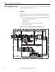
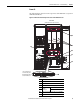
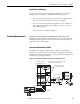
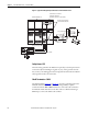
The following figure shows a basic one-line diagram for an AFE Frame 13 in a
IP21 Rittal enclosure. The main component sections consist of the following
items:
• AC Line Switchgear consisting of the input disconnect (Q0) and MCCB
motor-controlled circuit breaker (Q1)
• LCL Filter (L1)
• Precharge Circuit
• AFE power structure (U1) with AFE control assembly
• DC fuses (F2.1…F2.6)
Figure 23 - Basic One-line Diagram for an AFE Frame 13 in IP21 Rittal Enclosure
DC Bus
Output
L1
3 Phase
AC Input
L2
L3
PowerFlex
Active Front End System
Precharge
Circuit
R6.1
R6.2
+
-
AC Line
Switchgear
LCL Filter (L1)
AFE
Power Structure (U1)
DC
Fuses
U2
V2
W2
C1
C2
C3
C4
C5
C6
U1
V1
W1
Q1Q0
Precharge
Fuses
Precharge
Contactor
Motor Protection
Relay
Q5 K6F6
F2.1
F2.2
F2.3
F2.4
F2.5
F2.6
DC+
DC-
W
PE
PE
DC+
DC-
V
PE
DC+
DC-
U
PE