
Owner manual

Rockwell Automation Publication 20Y-UM001E-EN-P - July 2014 51
Chapter 2
AFE in IP21 Rittal Enclosure—Installation/
Wiring
This chapter provides information on installing and wiring the PowerFlex Active
Front End in a IP21 Rittal enclosure. For information on installing and wiring
the AFE in a IP20 2500 MCC Style enclosure, see Chapter
1.
Most start-up difficulties are the result of incorrect wiring. Every precaution must
be taken to verify that the wiring is done as instructed. All items must be read and
understood before the actual installation begins.
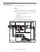
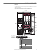
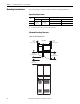
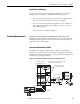
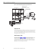
This section describes the main component sections and main component
locations of AFE Frame 10 and Frame 13 systems in a IP21 Rittal enclosure.
Topic Page
Main Component Sections
52
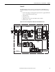
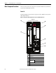
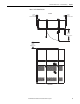
Main Component Locations
54
Mounting Considerations
56
AC Supply Source Considerations
58
Grounding Requirements
59
Fuses and Circuit Breakers
61
Power Wiring
61
Disconnecting Common Mode Capacitors
68
Using the AFE with PowerFlex Drives
72
Control Wiring
72
Precharging the AFE
78
CE Conformity
79
ATTENTION: The following information is merely a guide for proper installation.
Rockwell Automation cannot assume responsibility for the compliance or the
noncompliance to any code, national, local or otherwise for the proper
installation of this 700AFE or associated equipment. A hazard of personal injury
and/or equipment damage exists if codes are ignored during installation.