
Owner manual


Rockwell Automation Publication 20Y-UM001E-EN-P - July 2014 45
AFE in IP20 2500 MCC Style Enclosure—Installation/Wiring Chapter 1
Typical I/O Wiring
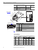
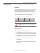
The IP20 2500 MCC Style enclosure for the AFE is factory wired and
programmed to operate from the operator switches on the front of the enclosure.
The AFE in the IP20 2500 MCC Style enclosure has an input contactor K1. The
AFE is configured to run when precharge is complete, the contactor is closed, and
no faults are present. The following figure shows the factory-installed wiring.
Figure 21 - Factory-installed Wiring Diagram for AFE in IP20 2500 MCC Style Enclosure
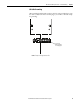
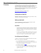
Analog I/O Configuration
Important: Analog I/O must be configured through programming, and the
jumpers shown below. See Figure 20
for jumper locations and
Table 8
for I/O jumper configurations.
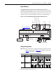
Table 8 - I/O Configuration for AFE in IP20 2500 MCC Style Enclosure
12345678 91011 12 13 14 15
14
K1K20
S11
11 14
13
K4
X3(64)
X3(63)
H5
FAULT
2
1
16 17
24V to LCL
18 19 20
20C-DPI1
Slot E (A13)
Input Contactor Supply
Input Contactor Close
Charging 1
Interlocker 2
20C-DO1
Slot B (A12)
20C-DA1-A
Slot A (A11)
AIA1+ AIA2-AIA1- AIA2+ -10Vref PotGND +10Vref AOUT1 AOUTC AOUT2 DIN1 DIN2 DIN3 DIN4 DIN5 DIN6 D_COM D_COM +24V 24VCOM
262524
21 22 23
R1 R2
K4
24V
R3R1
Input
Contactor
Control
Fault
Relay 4
24V DC
To User-supplied
Drive Inverter Enable Input
HIM Cradle (A14)
AFE On
Remote Fault Reset (optional)
Fault Reset
Input Contactor On Request
Input Contactor Acknowledge
LCL OverTemp
AFE Fault
K4
H3.1
READY
2
1
AFE Ready
X3(66) X3(65)
3
4
See Analog I/O Configuration on
page 45 for jumper settings.
Signal Jumper Setting
Analog
Inputs
J1 (Analog In 1)
J2 (Analog In 2)
0-20 mA 0-10V ±10V
Analog
Outputs
J3 (Analog Out 1)
J4 (Analog Out 2)
0-20 mA 0-10V ±10V
CDBA
J1 J2
CDBA
CDBA
J1 J2
CDBA
CDBA
J1 J2
CDBA
CDBA
J3 J4
CDBA
CDBA
J3 J4
CDBA
CDBA
J3 J4
CDBA